
Solar simulator light source with multiple lenses and multi-optical fiber coupling

A technology of solar simulator and optical fiber coupling, applied in the field of solar simulator light source, can solve the problems of wasting optical power and energy, increasing system heat generation, and large energy loss of light source, etc.

Inactive Publication Date: 2011-02-16
FUDAN UNIV
View PDF3 Cites 4 Cited by
  • Summary
  • Abstract
  • Description
  • Claims
  • Application Information

AI Technical Summary

Problems solved by technology

[0003] Since the solar simulator designed according to the above conventional method has a large loss of light source energy, in order to simulate sunlight to meet higher optical power output, a very high-power light source must be used, such as a lamp with a power of more than 1000 watts, but The volume and area of ​​the illuminant of high-power lamps are relatively large, so it is not an ideal point light source
Therefore, it will be difficult to obtain the simulated sunlight output characteristics of uniform distribution and low divergence angle through the transmission and mirror optical system designed according to the characteristics of point light source
Therefore, in practical applications, in order to obtain a simulated solar light source with uniform and low divergence angle output, an external diaphragm must not be added to significantly reduce the aperture of the light. In fact, the effective size of the illuminant is reduced to meet the optical principles of an ideal point light source. But at the cost of wasting more optical power and energy
In order to obtain high-power and large-area uniform low-divergence output simulated sunlight, the power of the lamp must be further increased, and the size of the light emitter of the lamp must be increased accordingly. However, limited by the size effect of the effective light emitter, the solar simulator The effective light output power is not directly proportional to the lamp power, but it significantly increases the heat generation of the system, which is a very low efficiency solar simulator application mode

Method used


Image

  • Solar simulator light source with multiple lenses and multi-optical fiber coupling
  • Solar simulator light source with multiple lenses and multi-optical fiber coupling
  • Solar simulator light source with multiple lenses and multi-optical fiber coupling

Examples


Embodiment Construction

[0017] The design of the present invention will be further described below in conjunction with the accompanying drawings and embodiments.

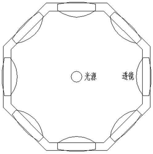
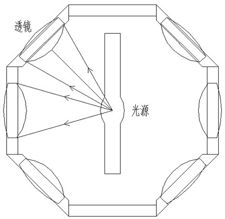
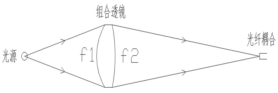
[0018] Such as Figure 1-3 shown. The specific implementation of the multi-lens (lens and mirror combination) and multi-fiber coupling light source collection device designed by the present invention is as follows (taking the coupling of the full lens combination and optical fiber as an example):

[0019] 1. Light source: A 75-watt high-voltage arc xenon lamp that can cover the spectral region from near-infrared to near-ultraviolet (200-1000nm wavelength) is used as the light source, and the arc length of the light is about 1.3mm.

[0020] 2. Use fused silica lens, diameter d=30mm, (or 30x30mm rectangular lens), focal length f 1 =30mm,f 2 =150mm.

[0021] 3. Use k=3 layer combination lens. The number of lenses in the center layer k1 is c1=8, the number of lenses in the upper and lower side layers k2 and k3 is c2=c3=4, and the total nu...


PUM


Abstract

The invention belongs to the technical field of optical electronic devices and in particular relates to a solar simulator light source with multiple lenses and multi-optical fiber coupling. In the invention, by utilizing the characteristic that a point light source has wider light-emitting opening angle in the cubical space, the high-efficiency utilization and output of light source energy is realized in the spatial light-emitting opening angle range of the light source by adopting the mode of the combination of multiple lenses and reflectors and the multi-optical fiber coupling. The invention is a novel solar simulation device and can be practically applied to the field of green energy sources, and the like.

Description

technical field [0001] The invention belongs to the technical field of optical and electronic devices, and in particular relates to a multi-mirror and multi-fiber coupling solar simulator light source. Background technique [0002] In the field of green solar energy and other fields, the development and application of various photoelectric conversion and photothermal conversion devices need to simulate the radiation spectrum of sunlight in an artificial experimental environment, and provide high-efficiency broad-spectrum sunlight simulation light sources from infrared to ultraviolet. The various light sources simulated and adopted generally have large stereoscopic luminous aperture angles. However, despite long-term efforts, research and use of light source collection systems with different structures, such as single-lens lighting with different focal lengths, or ellipsoidal , parabolic and other focusing mirrors improve the collection efficiency of the light source, but bec...

Claims


Application Information

Patent Timeline
IPC IPC(8): F21V17/00F21S8/00F21V19/00F21V13/00
Inventor 陈剑科陈良尧郑玉祥杨月梅
Owner FUDAN UNIV
Learn More