Check patentability & draft patents in minutes with Patsnap Eureka AI!

Tundish with pouring box body

A technology of tundish and box, which is applied in the direction of casting molten material container, metal processing equipment, casting equipment, etc. It can solve the problems of short residence time of molten steel, secondary oxidation of molten steel, and affecting product quality, so as to reduce slag entrainment Chance, increase residence time, reduce the effect of liquid level fluctuations

Active Publication Date: 2012-07-25
CHINA FIRST HEAVY IND
View PDF4 Cites 0 Cited by
  • Summary
  • Abstract
  • Description
  • Claims
  • Application Information

AI Technical Summary

Problems solved by technology

[0002]When the molten steel is poured in the existing tundish, the flow of the molten steel disturbs the liquid level of the molten steel in the tundish, and the steel slag formed on the surface of the molten steel will be impacted by the molten steel The slag that enters into the deep position below the liquid surface, especially the steel slag that enters the interior of the molten steel, is brought into the ingot mold by the flow field formed when the tundish nozzle is poured to produce slag; due to the impact on the surface of the molten steel when pouring the molten steel into the tundish, the middle The molten steel in the ladle cannot be protected by covering agent or mold slag, which will cause serious secondary oxidation of the molten steel; the residence time of the molten steel in the tundish is short, the temperature distribution is unreasonable, and the inclusions in the molten steel are easily Brought into the ingot mold by molten steel, affecting product quality

Method used


Image

  • Tundish with pouring box body
  • Tundish with pouring box body
  • Tundish with pouring box body

Examples


Embodiment Construction

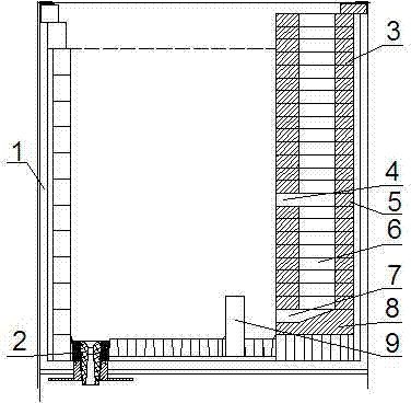
[0023] Such as figure 1 - figure 2 As shown, the package body 1 is circular, with a tundish spout 2 at the bottom, and a pouring box 10 on one side, and the casting box 10 is built by special-shaped bricks 1 , 2 special-shaped bricks 5 , and 3 special-shaped bricks Made, the pouring box 10 is provided with a pouring channel 6 in the middle, a molten steel outlet 7 is provided at the bottom, a flow steel hole 4 is provided in the middle, and a diversion dam 9 is provided at the front end of the molten steel outlet 7 at the bottom of the enclosure 1, and the diversion dam 9 is a The side is provided with leaking steel hole 11.

[0024] Such as image 3 - Figure 4 As shown, the special-shaped brick 3 is rectangular in shape, the front ends of the opposite sides are inclined inwardly, and a pouring channel 6 is provided in the middle.

[0025] Such as Figure 5 - Figure 6 As shown, the special-shaped brick 2 5 is rectangular in shape, and the front ends on both ...


PUM


Abstract

The invention discloses a tundish with a pouring box body and belongs to the technical field of vacuum ingot pouring. The tundish body is circular; a tundish water port is formed at the bottom of the tundish; and the pouring box body is arranged on one side of the tundish. The pouring box body is built by a first special brick, a second special brick and a third special brick; a pouring channel is formed in the middle of the pouring box body; a molten steel outlet is formed at the bottom of the pouring box body; a steel flowing hole is formed in the middle of the pouring box body; a guiding dam is formed at the front end of the molten steel outlet at the bottom of the tundish body; and a steel discharge hole is formed on one side of the guide dam. The pouring channel is formed inside the pouring box; liquid steel flows into the tundish from the bottom of the pouring channel so as to prevent the molten steel from back flowing on the surface in the tundish, the obviously turbulent part of the liquid steel is centralized on the steel pouring side and a steadily flowing molten bath is formed in the tundish. The guiding dam can block the flow of the molten steel along the bottom of thetundish, the flowing direction turns upward, the flow of the liquid steel of the tundish is improved, liquid level fluctuation in the tundish is reduced, the slag entrapment probability is reduced, the residence time of the liquid steel in the tundish is increased, the flotation of impurities is accelerated, a reasonable temperature distribution field is formed, and the inner quality of a steel ingot is improved.

Description

technical field [0001] The invention relates to a tundish with a pouring box and belongs to the technical field of vacuum ingot casting. Background technique [0002] When pouring molten steel in the existing tundish, the flow of molten steel disturbs the molten steel surface in the tundish, and the steel slag formed on the surface of the molten steel will be impacted by the molten steel into a deeper position below the liquid surface, especially into the interior of the molten steel The steel slag in the tundish is brought into the ingot mold by the flow field formed when the nozzle is poured into the tundish to produce slag curling; due to the impact on the surface of the molten steel when the molten steel is poured into the tundish, the molten steel in the tundish cannot be protected by covering agent or mold slag. The secondary oxidation of the molten steel is serious; the residence time of the molten steel in the tundish is short, the temperature distribution is unreaso...

Claims


Application Information

Patent Timeline
Patent Type & Authority Patents(China)
IPC IPC(8): B22D41/00
Inventor 赵林徐太安崔成万刘海澜张凤喜
Owner CHINA FIRST HEAVY IND
Features
  • R&D
  • Intellectual Property
  • Life Sciences
  • Materials
  • Tech Scout
  • Unparalleled Data Quality
  • Higher Quality Content
  • 60% Fewer Hallucinations
Learn More