Experimental device of free surface vortex forming and evolving mechanism

An experimental device and vortex technology, which is used in the research field of free surface flow in fluid mechanics, can solve problems such as undeclared patents, and achieve the effects of low cost, convenient and fast experimental observation and measurement, and small volume.

Inactive Publication Date: 2011-02-23
SHANGHAI UNIV
View PDF5 Cites 9 Cited by
  • Summary
  • Abstract
  • Description
  • Claims
  • Application Information

AI Technical Summary

Problems solved by technology

[0003] In order to verify the results of theoretical analysis and numerical simulation, starting from the needs of mechanism r

Method used


Image

  • Experimental device of free surface vortex forming and evolving mechanism
  • Experimental device of free surface vortex forming and evolving mechanism
  • Experimental device of free surface vortex forming and evolving mechanism

Examples


Embodiment 1

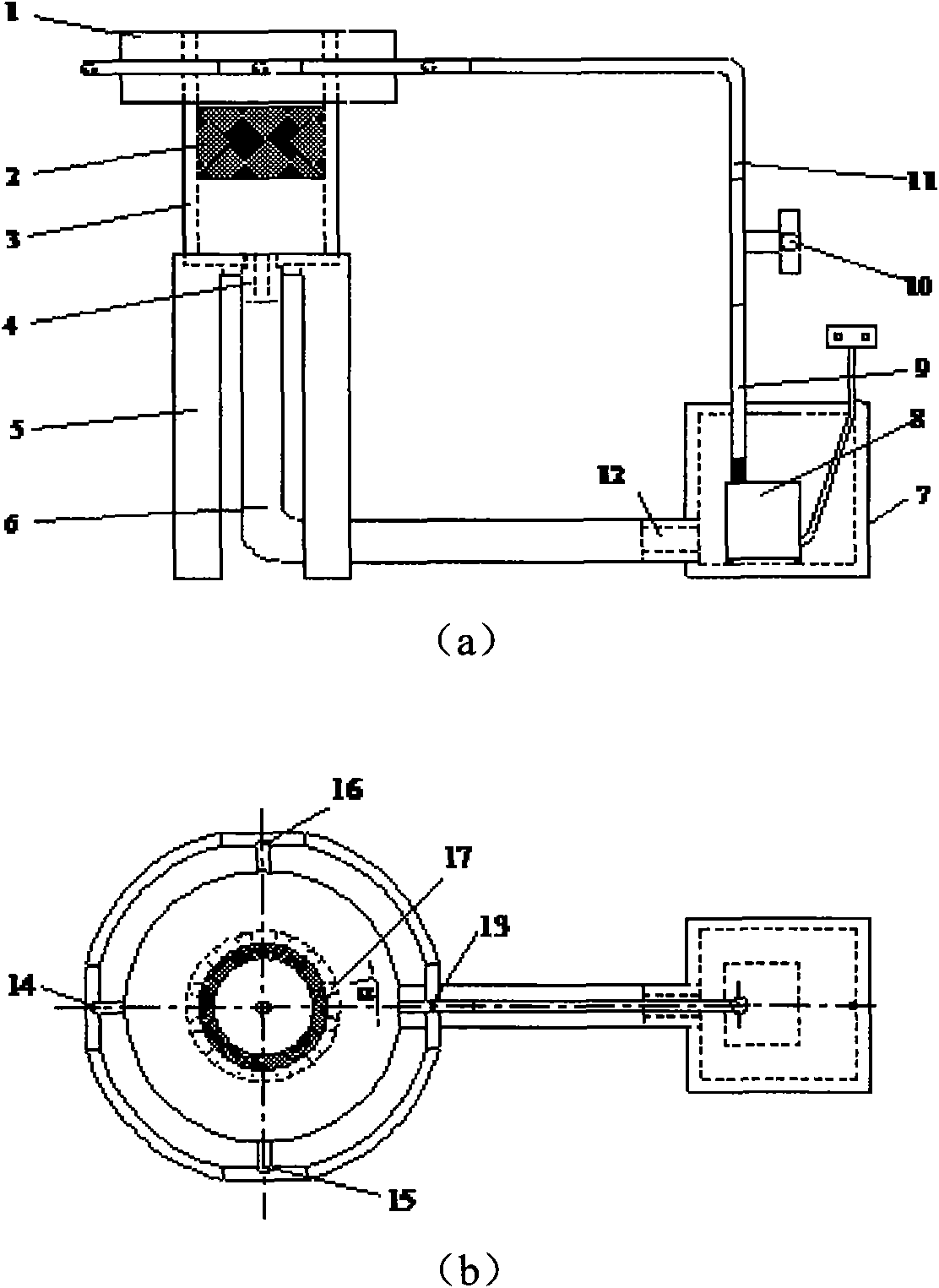
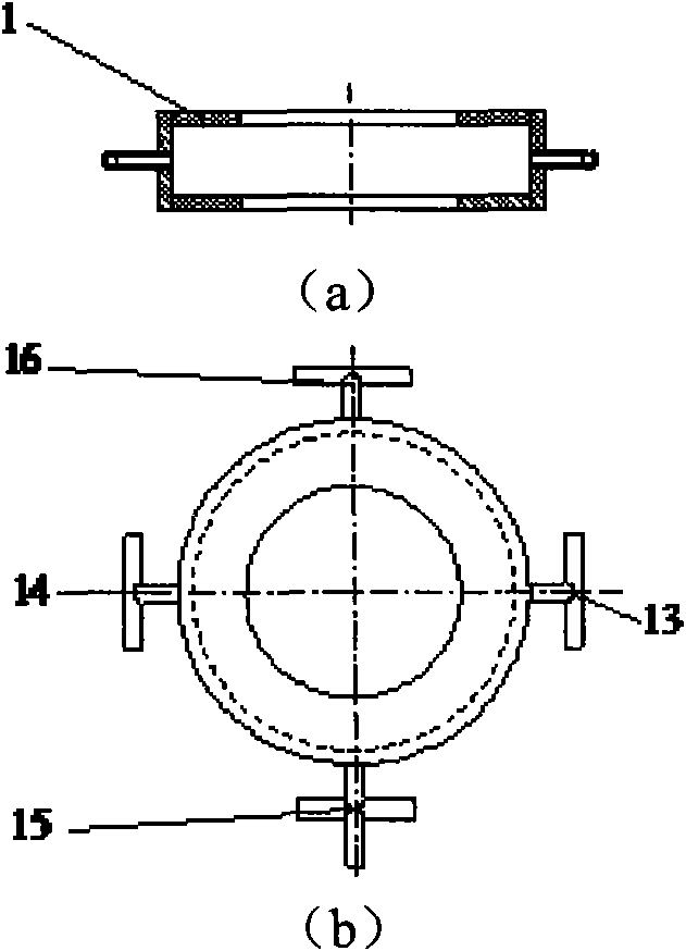
[0021] Embodiment one: with reference to attached figure 1 , the experimental device for the study of the free surface vortex formation and evolution mechanism, including a cylinder 3, a sealed water tank 7, a micropump 8, a flow regulating valve 10 and a water inlet buffer chamber 1, the upper part of the cylinder 3 is connected to the water inlet buffer chamber 1 are bonded together, and a sponge ring 2 is installed on the inner side of the cylinder wall of the cylinder 3 to stabilize the flow and increase the resistance. The water pipe joint 14 is connected through the thick pipeline 6; the micropump 8 is bonded to the bottom of the sealed water tank 7, and the water outlet of the micropump 8 is connected to the flow control valve 10 through the pipeline 9, and the flow control valve 10 is connected to the flow control valve 10 through the pipeline. 11 is connected to an inflow port 13 of the water inlet buffer chamber 1 through a four-way pipe joint, and the four-way pipe ...

Embodiment 2

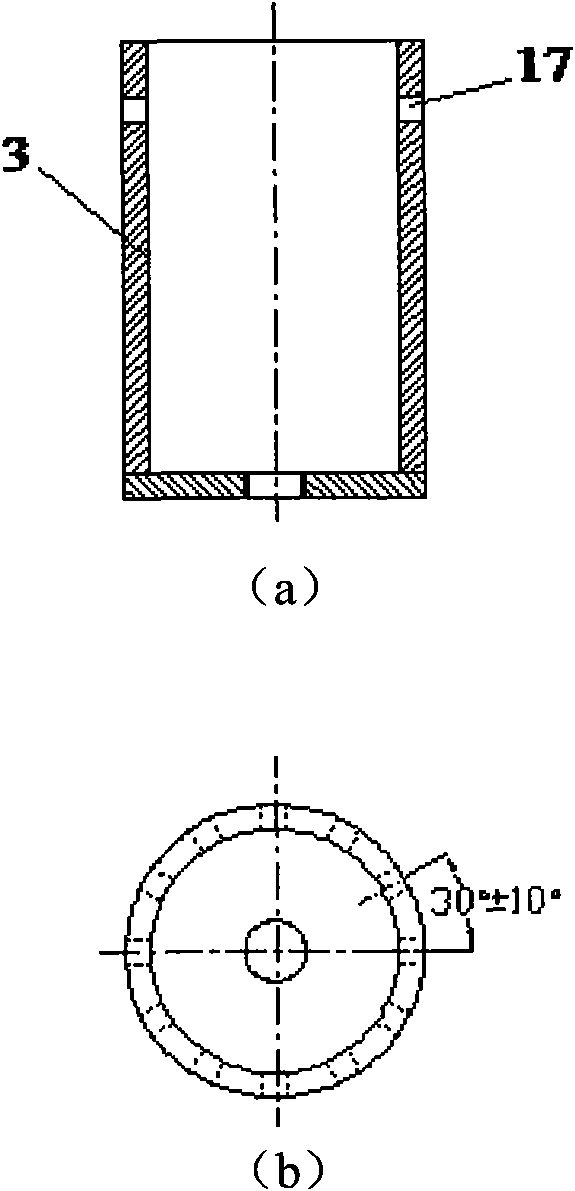
[0022] Embodiment two: this embodiment is basically the same as embodiment one, and the special features are as follows: figure 1 , figure 2 , image 3 with Figure 4 , the water inlet pipes 13, 14, 15, 16 uniformly distributed in the circumferential direction of the water inlet buffer chamber 1 and the inflow hole 17 on the upper part of the cylinder 3 are misaligned. The upper opening of the cylinder 3 communicates with the outside atmosphere, and the bottom is provided with an internal thread to be screwed with the outlet pipe joint 4 . The cylinder 3 is supported by a support frame 5 , and the top of the support frame 5 has a circular groove to be arranged with the cylinder 3 . The outlet pipe joint 4 is connected to the water outlet of the cylinder 3 through a sealing ring to ensure no leakage; the outlet pipe joint 4 is a group except the inner aperture (d 2 ), other structural dimensions (H, D, d 1 ) consistent series of fittings. Except the micropump 8, the conn...


PUM


Abstract

The invention relates to an experimental device of a free surface vortex forming and evolving mechanism. The device comprises a cylinder, a sealed water tank, a micro pump, a flow adjusting valve and a water inlet buffer chamber, wherein the upper part of the cylinder is adhered to the water inlet buffer chamber; a resistance increasing sponge ring used for flow stabilization is arranged on the inner side of the wall of the cylinder; the bottom of the cylinder is connected with a water outlet pipe joint; the water outlet pipe joint is connected with a water inlet pipe joint of the sealed water tank through a rough pipeline; the micro pump is adhered to the bottom of the sealed water tank; a water outlet of the micro pump is connected with a flow control valve through a pipeline; the flow control valve is connected with a flow inlet of the water inlet buffer chamber through a four-way pipe joint; the four-way pipe joint is connected with another three flow inlets which are uniformly distributed on the water inlet buffer chamber along the circumferential direction through three three-way pipe joints; and the flow inlets which are uniformly distributed on the wall of the cylinder along the circumferential direction are communicated with the water inlet buffer chamber.

Description

technical field [0001] The invention relates to the research field of free surface flow problems in fluid mechanics, in particular to an experimental device for studying the formation and evolution mechanism of free surface vortices. Background technique [0002] The free surface vortex is a common hydraulic phenomenon in front of the water intake of hydraulic structures, and it sometimes occurs on the upstream surface of the water intake of hydropower stations, spillways, diversion tunnels, pumping stations, and ship locks. According to the development degree of the free surface vortex, there are many classification methods, among which the classification method of the Alden Laboratory of the Worcester General Research Institute in Massachusetts is relatively clear, and it is divided into six basic types: surface vortex, surface vortex, dyed vortex, entrained vortex, and surface vortex. The material vortex, intermittent suction vortex and continuous suction vortex, especial...

Claims


Application Information

Patent Timeline
IPC IPC(8): G01M10/00
Inventor 陈红勋张睿胡雷
Owner SHANGHAI UNIV
Why Eureka
Try Eureka