Capillary array

a capillary array and capillary technology, applied in the field of capillary arrays, can solve the problems of complicated optical measurement perpendicular to the longitudinal axis of the capillary, and achieve the effect of convenient manual handling and advantageous automation

Active Publication Date: 2015-05-21
NANOTEMPER TECH GMBH +1
View PDF6 Cites 7 Cited by
  • Summary
  • Abstract
  • Description
  • Claims
  • Application Information

AI Technical Summary

Benefits of technology

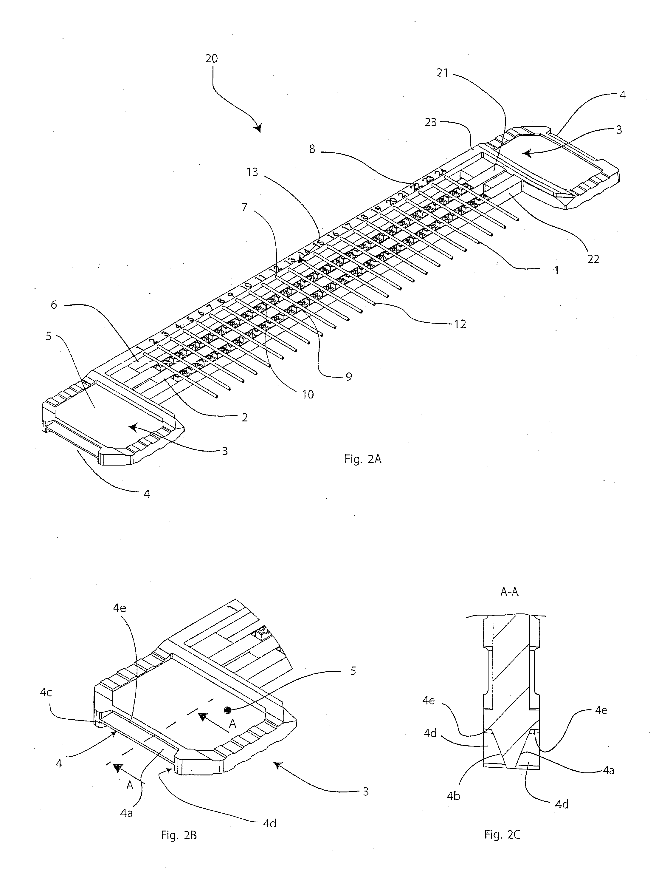
[0059]It may further be advantageous for automation when the array has surfaces and/or structures for grabbing and/or movement by a robot. The array may for example have bevels on at least one side, preferably on two (opposite) sides, which may be grabbed by a corresponding fit (form fit) in a robotic grabber.
[0060]Preferably the array has surfaces (grabbing surfaces) w...

Problems solved by technology

Further, the array on which the capillaries are attached or fixed should not be completely impervious or opaque to ...

Method used


Image

  • Capillary array
  • Capillary array
  • Capillary array

Examples


Embodiment Construction

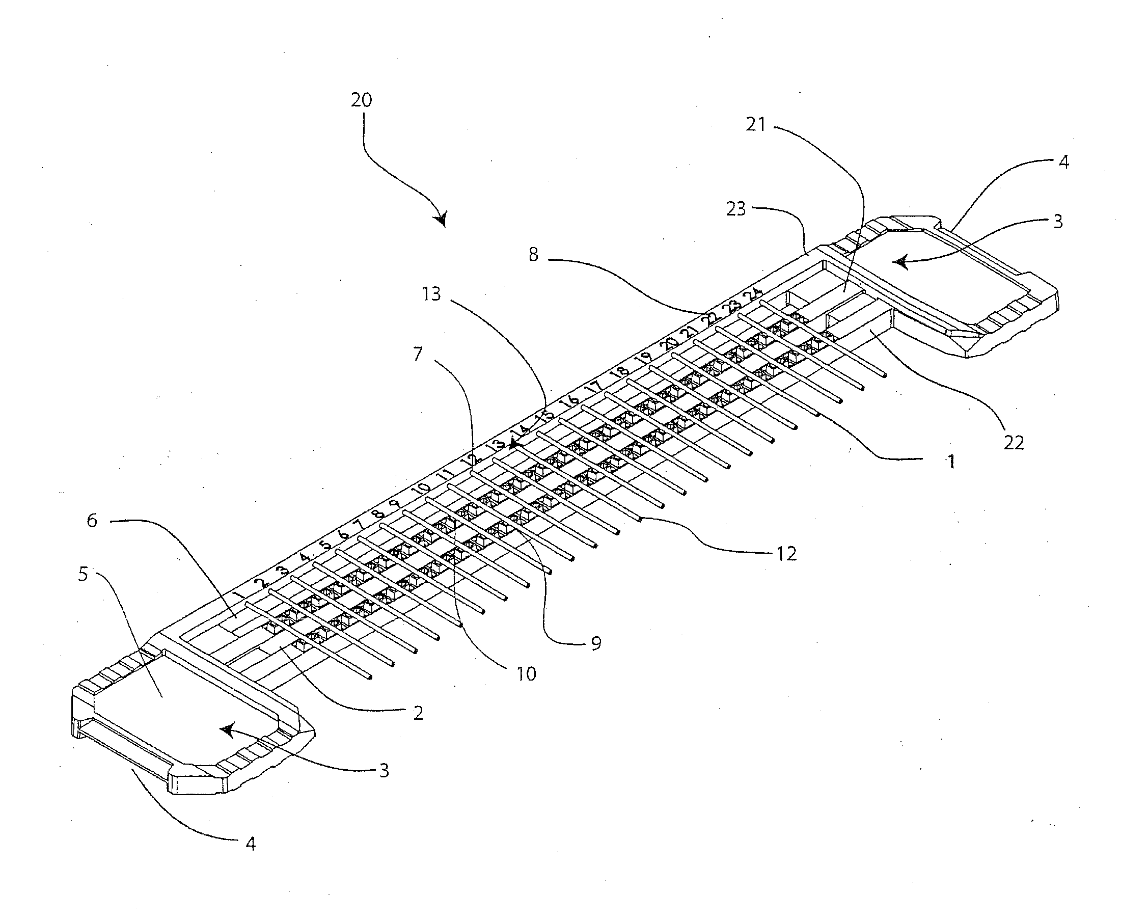
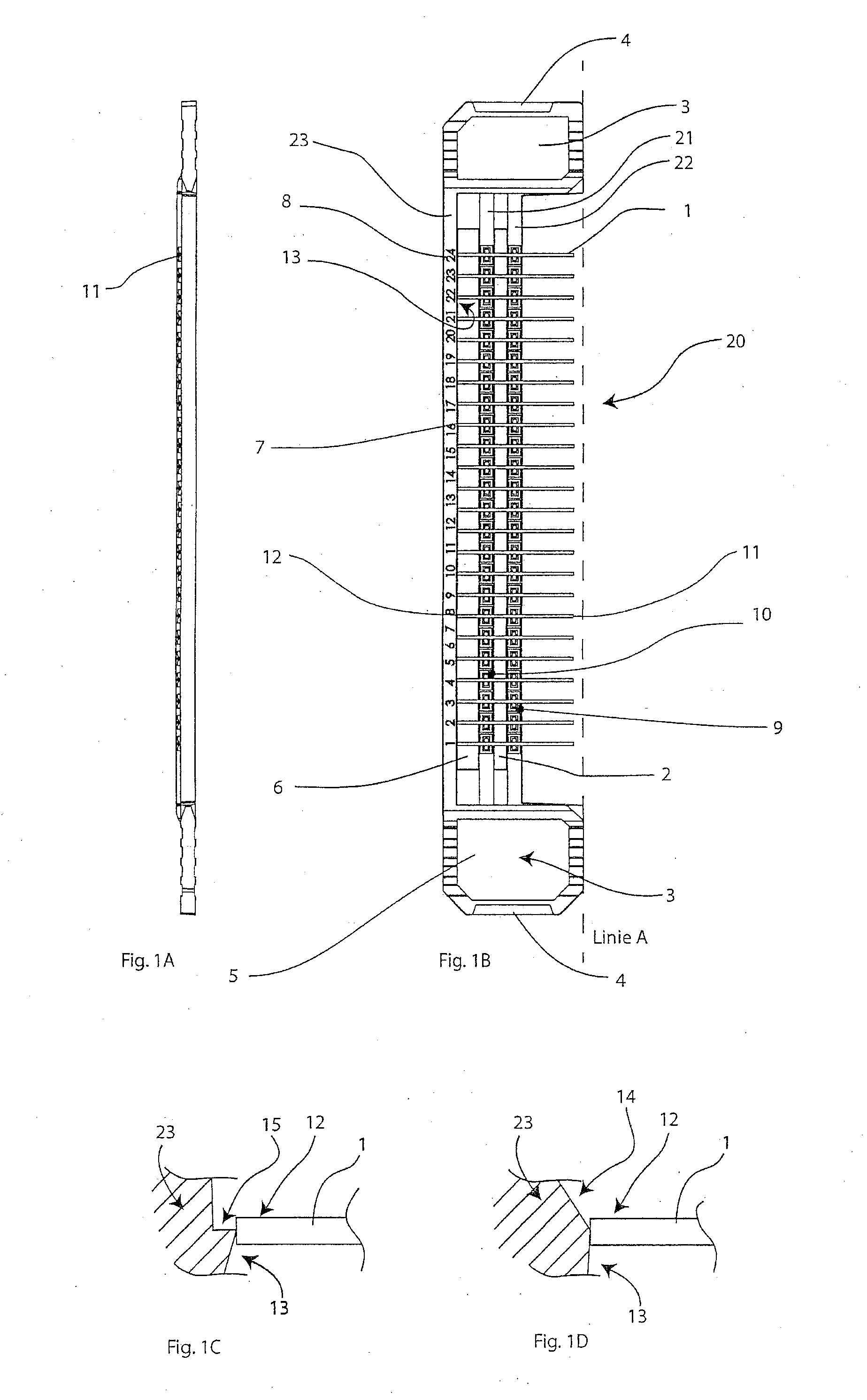
[0148]FIG. 1B schematically shows an exemplary embodiment of an array 20 according to the present invention in a top view. 24 capillaries 1 with a consistent distance of about 4.5 mm are attached to the array in a common plane, wherein the common plane lies parallel to or in the paper plane. In particular, the common plane is visible in the side view of FIG. 1A. The array has substantially two, preferably approximately parallel mounting struts 21, 22. Preferably, each capillary 1 is attached / fixed to both mounting struts, i.e. each capillary is mounted to the array at least at two points 9, 10 being spaced apart from each other, which enables a secure mounting. Preferably, both mounting struts 21, 22 are being spaced apart from each other. Preferably, the measuring slot / the measuring window 2, which enables light to be transmitted through the individual capillaries perpendicular to the common plane, is positioned between both mounting struts. For example, the measuring slot / measurin...


PUM


Abstract

The invention relates to arrays with a plurality of capillaries being arranged in a plane and mechanically attached to the array, wherein the distance of adjacent capillaries is approximately 2.25 mm or an integer multiple thereof. At least one free end of each capillary projects from the array in such a way that the free ends of the capillaries may be simultaneously inserted into wells of a microwell plate.

Description

[0001]The present invention generally relates to a capillary array. In particular, the invention relates to an array for a plurality of capillaries by means of which a simultaneous filling of a plurality of capillaries of a microwell plate is made possible. Furthermore, the invention also relates to an apparatus and a method for filling, transportation and measurement of fluids having volumes at microlitre levels.BACKGROUND OF THE INVENTION[0002]NanoTemper Technologies GmbH develops and sells measurement devices, by means of which liquids within a capillary are examined or analyzed optically. It is further known that a single capillary is taken by hand, immersed into a liquid and then separately put down on an array and subsequently pushed into the measuring device. Said method of filling individual capillaries is shown for example in a video of NanoTemper Technologies GmbH, which is published under http: / / www.youtube.com / watch?v=rCot5Nfi_Og. The individual filling is advantageous f...

Claims


Application Information

Patent Timeline
IPC IPC(8): G01N21/03G01N21/11G01N21/13G01N21/71
CPCG01N21/03G01N21/71G01N2201/02G01N21/13G01N2201/04G01N21/11B01L7/00B01L9/065B01L2300/0838B01L2400/0406
Inventor BAASKE, PHILIPPDUHR, STEFANREICHL, STEFANBIGUS, HANS-JURGEN
Owner NANOTEMPER TECH GMBH
Why Eureka
Try Eureka