An electrocoagulation cell

An electrocoagulation and electrode technology, applied in chemical instruments and methods, water/sludge/sewage treatment, sterilization/microdynamic water/sewage treatment, etc., can solve problems such as poor electrical contact, waste of space, and adverse effects. Achieve the effect of relative voltage drop and low resistance

Inactive Publication Date: 2011-02-23
ENVA IRELAND LTD
View PDF4 Cites 2 Cited by
  • Summary
  • Abstract
  • Description
  • Claims
  • Application Information

AI Technical Summary

Problems solved by technology

As with the electrocoagulation cell of U.S. Patent No. 6,139,710, the wire connections are rather space consuming, thus limiting the number of electrodes that can be accommodated in the cell
The electrical contact to the anode is apparently via a spring which would result in a poor electrical contact and therefore adversely affect the efficiency of the unit
[0015] The use of the electrocoagulation cell described above for industrial purposes is hampered by its aforementioned limitations
Furthermore, the maximum current that can be applied to these units is about 300 amps, and this limitation adversely affects the amount of liquid that can be effectively processed in a given period

Method used


Image

  • An electrocoagulation cell
  • An electrocoagulation cell
  • An electrocoagulation cell

Examples


Embodiment 1

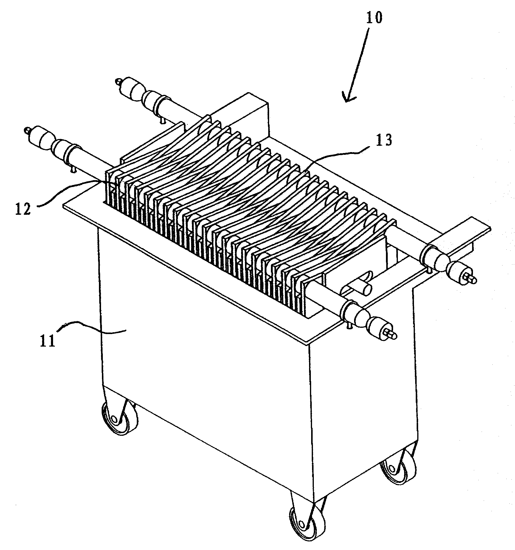
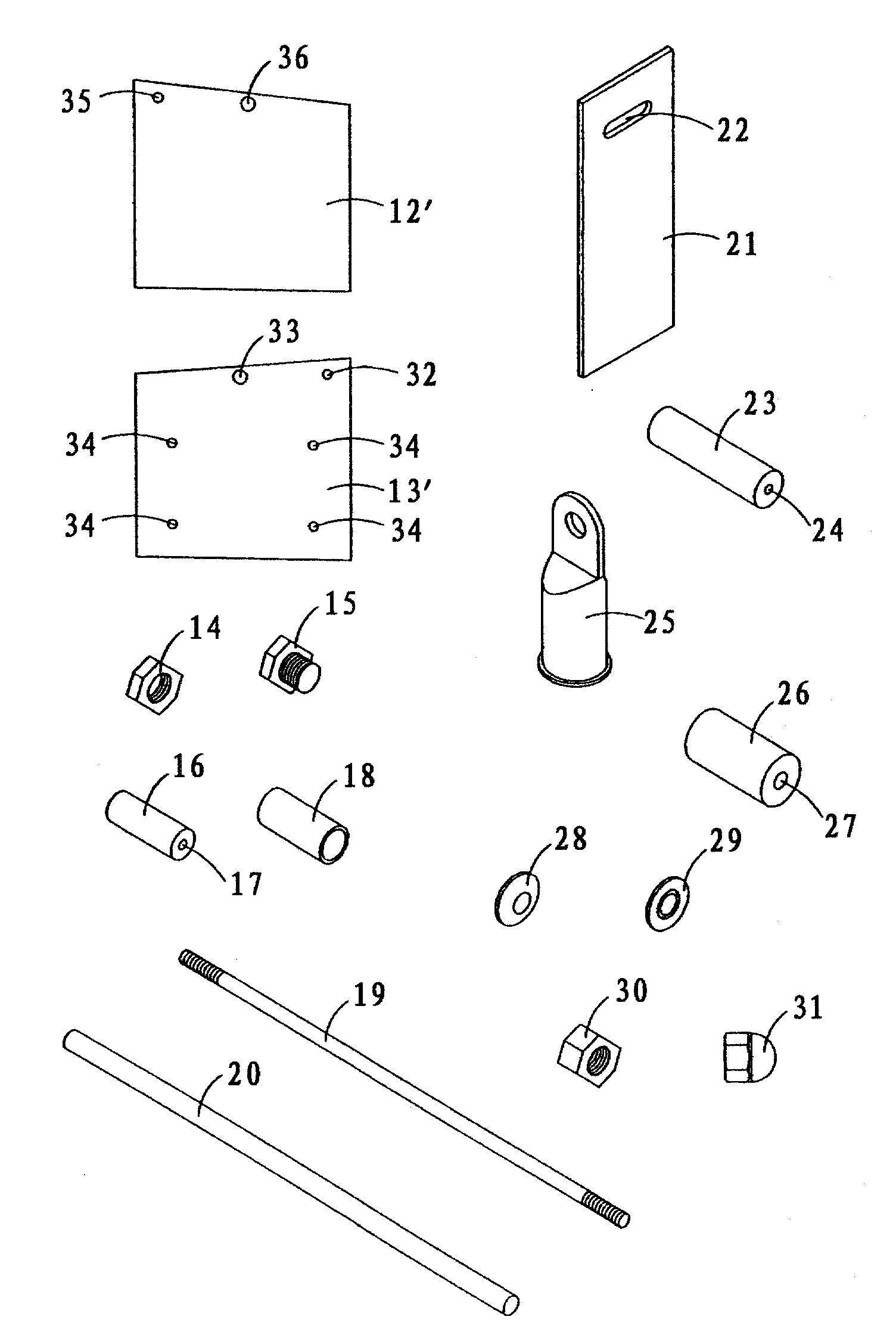
[0117] Assembled as described above with a first group of twenty-one aluminum electrodes 12' and a second group of twenty aluminum electrodes 13', such as figure 1 The electrocoagulation unit 10 is shown, and the electrocoagulation unit 10 is connected to the spraying system 45 . The electrocoagulation cell 10 is connected to a rectifier 56 . The positive terminal of the rectifier 56 is connected to the electrical connector 25 provided at either end of the first connecting rod 19 and the negative terminal of the rectifier 56 is connected to the electrical connector 25 provided at either end of the second connecting rod 19 .

[0118] Let 800 amperes flow into the electrocoagulation unit 10, where 400 amperes pass through the aluminum feed sleeve 23 provided at one end of the first connecting rod 19 and 400 amperes pass through the other end of the first connecting rod 19 The aluminum feed bushing 23 of the electrode flows in such that each electrode 12' disposed on the first c...

Embodiment 2

[0123] Four electrocoagulation cells 10 - each having a first set of twenty-one aluminum electrodes 12' and a second set of twenty aluminum electrodes 13' - were assembled as described above and connected to the spray System 45 and with Figure 8 In the same manner as the electrocoagulation unit 10 in the electric coagulation unit, it is arranged in the form of electrical series connection and liquid parallel connection.

[0124] The positive terminal of the rectifier 56 is connected to the electrical connection 25 provided at either end of the connecting rod 19 of the first electrocoagulation cell 10 . Connect the electrical connection piece 25 provided at any end of the other connecting rod 19 of the first electrocoagulation unit to the electrical connection device 25 provided at any end of the connecting rod 19 of the second electrocoagulation unit 10 . The second electrocoagulation unit 10 is connected to the third electrocoagulation unit 10, and the third electrocoagulat...

Embodiment 3

[0131] Four electrocoagulation cells 10 - each having a first set of twenty-one aluminum electrodes 12' and a second set of twenty aluminum electrodes 13' - were assembled as described above and connected to the spray System 45 and with Figure 8 In the same manner as the electrocoagulation unit 10 in the electric coagulation unit, it is arranged in the form of electrical series connection and liquid parallel connection. The amount of current flowing into the electrocoagulation cell 10 varies between 400-450 amperes due to variations in the flow rate of liquid flowing into the cell 10 . Electric current flows into and through the electrocoagulation cell 10 in the same manner as described in Example 1 and Example 2.

[0132] 36-39m from glass cutting operations 3 / hour of effluent is pumped through the electrocoagulation cell 10 . The effluent contained 800-1000mg / litre of suspended glass slag and 40-60mg / litre of dissolved lead. The electrocoagulation unit 10 worked contin...


PUM


Abstract

An electrocoagulation cell (10) has a reaction chamber (11) in which are assembled a first set of electrodes (12) interleaved with a second set of electrodes (13). Each set of electrodes (12, 13) is connected together by a separate tie-bar (19), which passes through each electrode (12', 13', respectively), and an electrically conductive bush (not shown), positioned between the electrodes (12', 13') in each set. Each electrically conductive bush is covered by a polypropylene shield (18). The sets of electrodes (12, 13) are further supported on two pedestals (37) and a non-conductive support rod (20). Separation of the electrodes (12', 13') within the reaction chamber (11) is maintained by four nylon nuts (not shown) and bolts (not shown), which pass through each electrode (13'). The first set of electrodes (12) is connected at each end (41) of the tie- bar (19) to one pole of a power supply through electrical connectors (25) and the second set of electrodes (13) is connected at each end of the tie- bar (19) to the other pole of the power supply through electrical connectors (25). Due to the arrangement of the tie-bars (19) and the electrically conductive bushes (16) the necessity of connecting each electrode (12', 13'') directly to the power supply is obviated and leads to a saving of space and a close packing of the electrodes (12', 13') within the reaction chamber (11). This results in a good ratio between the surface area of the electrodes (12', 13') and a volume of liquid passing through the reaction chamber (11) in use, resulting in an efficient electrocoagulation process.

Description

technical field [0001] The present invention relates to an electrocoagulation cell, in particular, the present invention relates to an electrocoagulation cell used in industrial processes such as waste liquid treatment. Background technique [0002] Electrocoagulation is an electrolytic treatment method used to separate and remove a wide variety of contaminants including metals, solids, pathogens and other undesirable substances from solutions. Typically, an electrocoagulation cell contains electrodes and an electrolyte to be processed. The treatment process can be performed in various ways depending on the nature of the electrolyte. [0003] US Patent No. 6,139,710 discloses an electrocoagulation cell in which a plurality of substantially parallel electrodes are mounted in the flow path of a solution to be electrolyzed. Electrodes are unipolar (anode or cathode) and bipolar (anode and cathode). Both electrode surfaces of a bipolar electrode react with an electrolytic sol...

Claims


Application Information

Patent Timeline
Patent Type & Authority Applications(China)
IPC IPC(8): C02F1/463C02F1/467C02F1/461
CPCC02F1/463C02F1/4672C02F1/46114
Inventor 弗兰克·斯坦利·霍兰
Owner ENVA IRELAND LTD
Why Eureka
Try Eureka