Inductive power transfer

A power transmission, power technology, applied in the direction of inductors, transportation and packaging, safety/protection circuits, etc., can solve problems such as complex conflict detection

Inactive Publication Date: 2011-02-23
ACCESS BUSINESS GRP INT LLC
View PDF6 Cites 48 Cited by
  • Summary
  • Abstract
  • Description
  • Claims
  • Application Information

AI Technical Summary

Problems solved by technology

This can be a complex technique and may require some degree of collision detection e.g. in the presence of multiple secondary units

Method used


Image

  • Inductive power transfer
  • Inductive power transfer
  • Inductive power transfer

Examples


Embodiment Construction

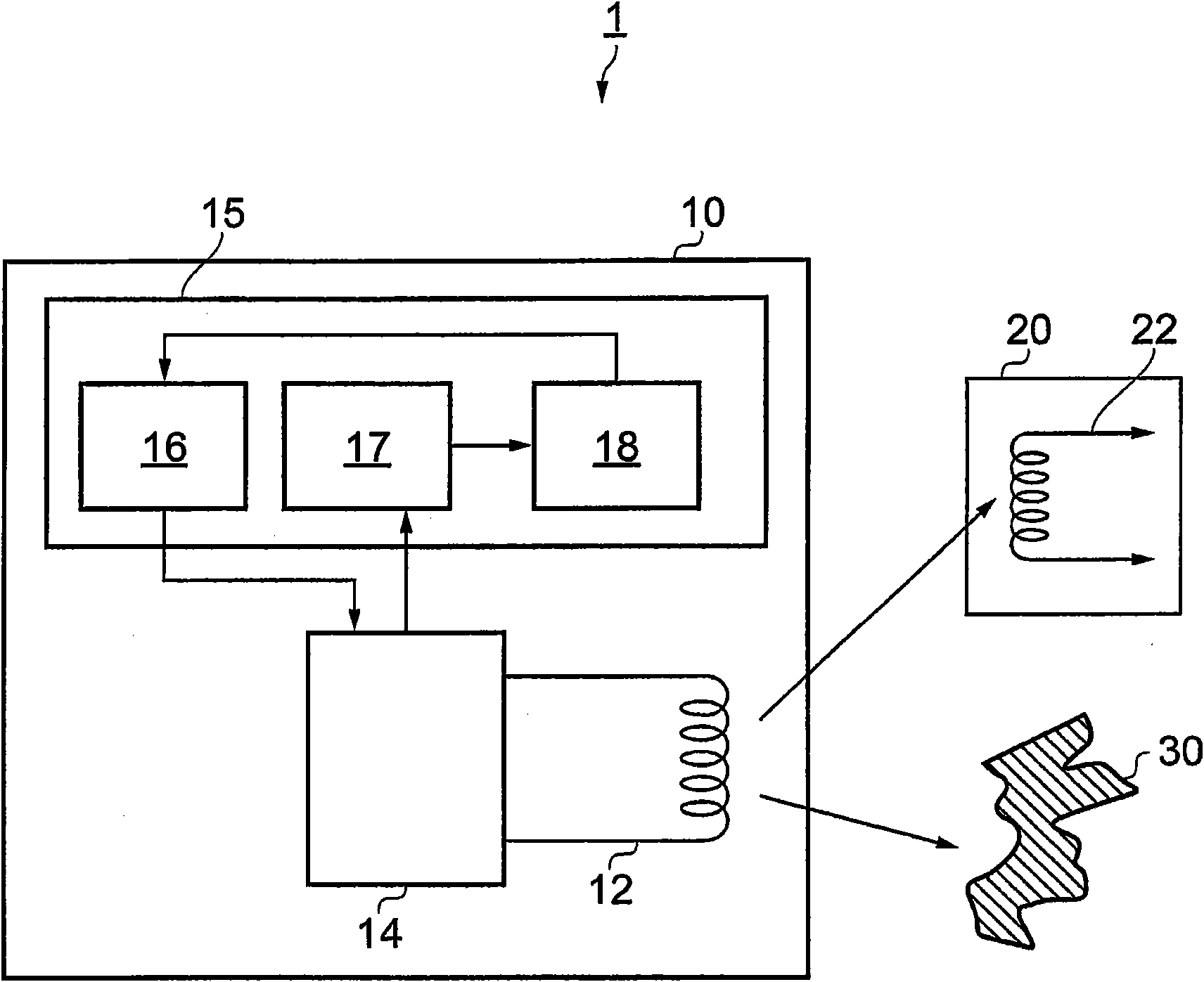
[0113] figure 1 is a schematic diagram of elements of an inductive power transfer system 1 according to an embodiment of the invention. The system 1 comprises a primary unit 10 and at least one secondary unit 20 . The primary unit 10 itself also embodies the invention.

[0114] The primary unit 10 comprises a primary coil 12 and an electric drive unit 14 connected to the primary coil 12 to apply an electric drive signal thereto in order to generate an electromagnetic field. A control unit 15 is connected to this electric drive unit 14 and comprises an adjustment unit 16 , an evaluation unit 17 and a detection unit 18 .

[0115] The adjustment unit 16 is connected to the electric drive unit 14 to adjust or control the electric drive signal or at least one electric drive signal applied to the primary coil 12 . An evaluation unit 17 is connected to the electric drive unit 14 to evaluate the amount of power drawn from the primary coil via the generated electromagnetic field. T...


PUM


Abstract

A detection method for use in a primary unit of an inductive power transfer system, the primary unit being operable to transmit power wirelessly by electromagnetic induction to at least one secondary unit of the system located in proximity to the primary unit and / or to a foreign object located in said proximity, the method comprising: driving the primary unit so that in a driven state the magnitude of an electrical drive signal supplied to one or more primary coils of the primary unit changes from a first value to a second value; assessing the effect of such driving on an electrical characteristic of the primary unit; and detecting in dependence upon the assessed effect the presence of a said secondary unit and / or a foreign object located in proximity to said primary unit.

Description

technical field [0001] The present invention relates to inductive power transfer methods, devices and systems for eg powering portable electrical or electronic equipment. Background technique [0002] An inductive power transfer system suitable for powering portable devices can consist of two parts: [0003] • A primary unit with at least one primary coil through which an alternating current is driven, creating a time-varying magnetic flux. [0004] • A secondary unit separate from said primary unit, said secondary unit having a secondary coil. [0005] When the secondary coil is placed near the time-varying flux produced by the primary coil, the varying flux induces an alternating current in the secondary coil and thus power can be inductively transferred from the primary unit to transmitted to the secondary unit. [0006] In general, the secondary unit supplies the transferred power to an external load, and the secondary unit may be hosted in or by a host object (second...

Claims


Application Information

Patent Timeline
Patent Type & Authority Applications(China)
IPC IPC(8): H02J5/00
CPCH02J7/025H02J5/005H02J7/045Y02T90/12Y02T10/7072Y02T90/14B60L53/124B60L53/126B60L53/122Y02T10/70H02J7/04H02J50/402H02J50/80H02J7/00714H02J50/90H02J7/007182H02J50/12H02J50/15H02J50/30H02J50/40H02J50/60B60L53/12B60L53/30H01F38/14H02J7/0029Y04S30/12Y02T90/167
Inventor J·R·迪本W·H·莱门斯D·J·霍夫H·肯努德特J·德克勒克
Owner ACCESS BUSINESS GRP INT LLC
Why Eureka
Try Eureka