Electric machine tool

A technology for electric tools and motors, applied in the direction of manufacturing tools, electric components, electrical components, etc., can solve problems such as cumbersome, space problems, and troublesome brush replacement, and achieve the effect of simple methods and methods, and space saving.

Inactive Publication Date: 2011-02-23
ROBERT BOSCH GMBH
View PDF1 Cites 5 Cited by
  • Summary
  • Abstract
  • Description
  • Claims
  • Application Information

AI Technical Summary

Problems solved by technology

With regard to the ever-increasing power density and compactness of conventional electric power tools, this leads to space problems due to the available installation space.
In addition, when replacing the brushes, the screw connection must be dismantled separately for each commutator brush to be replaced, which results in a cumbersome and labor-intensive brush replacement

Method used


Image

  • Electric machine tool
  • Electric machine tool
  • Electric machine tool

Examples


Embodiment Construction

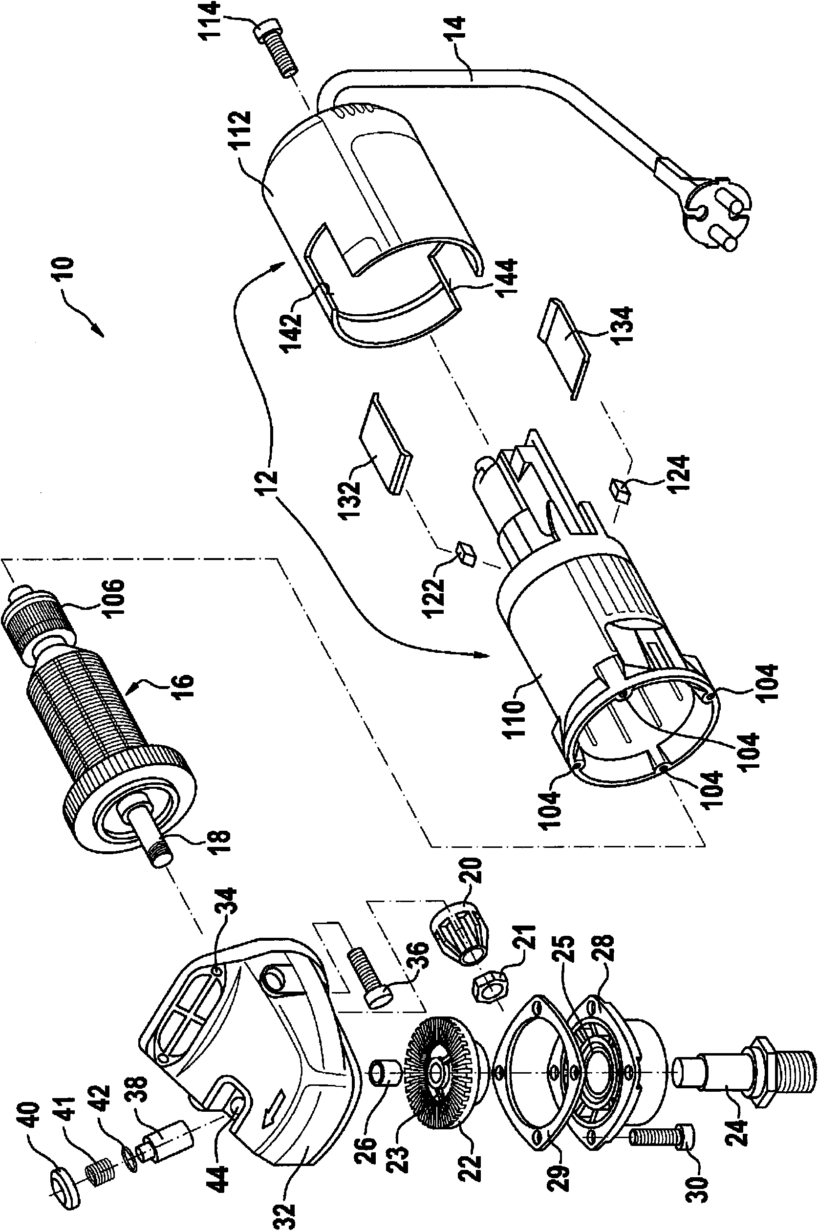
[0026] figure 1 An angle grinder 10 is shown according to an exemplary embodiment of the invention, which is constructed in the form of a pot and has an elongated, pot-shaped housing 12 . Inside the housing 12 a rotor 16 can be mounted with a motor shaft 18 on which a bevel gear 20 can be screwed axially by means of a nut 21 . The bevel gear 20 is intended to engage in the toothing of a disk gear 22 which has stop recesses 23 on its toothing side, which are formed by pressed-in recesses.

[0027] The disk gear 22 is mounted in a rotationally fixed manner on a drive shaft 24 which extends at right angles to the motor shaft 18 . The axial end region of the drive shaft 24 is surrounded by a bearing sleeve 26 which is arranged in an associated bearing bore of the transmission housing 32 . The other axial end region of the drive shaft is supported in a ball bearing 25 which is arranged in a bearing flange 28 . This bearing flange is screwed to the underside of the transmission h...


PUM


Abstract

In the case of an electric machine tool with a commutator motor which has a motor shaft (18) which is arranged rotatably in a motor housing (110) and has a commutator (106), to which at least two commutator brushes (122, 124) are assigned which are accessible via at least one brush cover (132, 134) provided on the motor housing (110), a covering element (112) fixes the brush cover (132, 134) on the motor housing (110) in an operating position in which the commutator brushes (122, 124) are covered, wherein the covering element (112) is fastened on the motor housing (110) via a detachable connection.

Description

technical field [0001] The invention relates to an electric power tool with a commutator motor, which has a motor shaft rotatably arranged in a motor housing with a commutator, to which at least two commutator brushes are attached, which pass through at least one The brush cover on the motor housing is accessible. Background technique [0002] Such an electric power tool is described in DE 36 35 067 A1. It has two diametrically opposite commutator brushes on the commutator, which are guided axially displaceably in associated brush holders. Each brush holder is accessible through a housing opening provided on the motor housing, in which a respective brush cover is arranged. In the brush cover's operating position, each brush cover is closed against the motor housing by means of an associated screw connection, thereby covering the commutator brushes. To replace the brushes, the screw connection of the brush cover must be disassembled in order to open the cover or to remove ...

Claims


Application Information

Patent Timeline
Patent Type & Authority Applications(China)
IPC IPC(8): H02K5/14
CPCH02K7/145H02K5/143H02K5/10B25F5/02
Inventor J·莫特F·埃森韦因A·霍夫曼T·肖米希
Owner ROBERT BOSCH GMBH
Why Eureka
Try Eureka