Cable fixing clamp

A technology for fixing clips and cables, applied in the direction of electrical components, etc., can solve the problems of the insulation layer of the easy-to-wear lines, no room for adjustment, short-circuit accidents of transmission lines, etc., to achieve excellent electrical performance, solve performance reliability problems, Easy to process effect

Inactive Publication Date: 2011-03-02
CHINA CNR LIMITED DALIAN ELECTRIC TRACTION R&D CENT
View PDF8 Cites 11 Cited by
  • Summary
  • Abstract
  • Description
  • Claims
  • Application Information

AI Technical Summary

Problems solved by technology

[0005] 1. It can only be applied to cables of one specification, and there is no room for adjustment;
[0006] 2. Only one cable can be fixed at a time, and the operation efficiency is low;
[0007] 3. There are great defects in the protection of cables, and it is easy to wear the insulation layer of the line after long-term work, resulting in short-circuit accidents in the transmission line

Method used


Image

  • Cable fixing clamp
  • Cable fixing clamp
  • Cable fixing clamp

Examples


Embodiment Construction

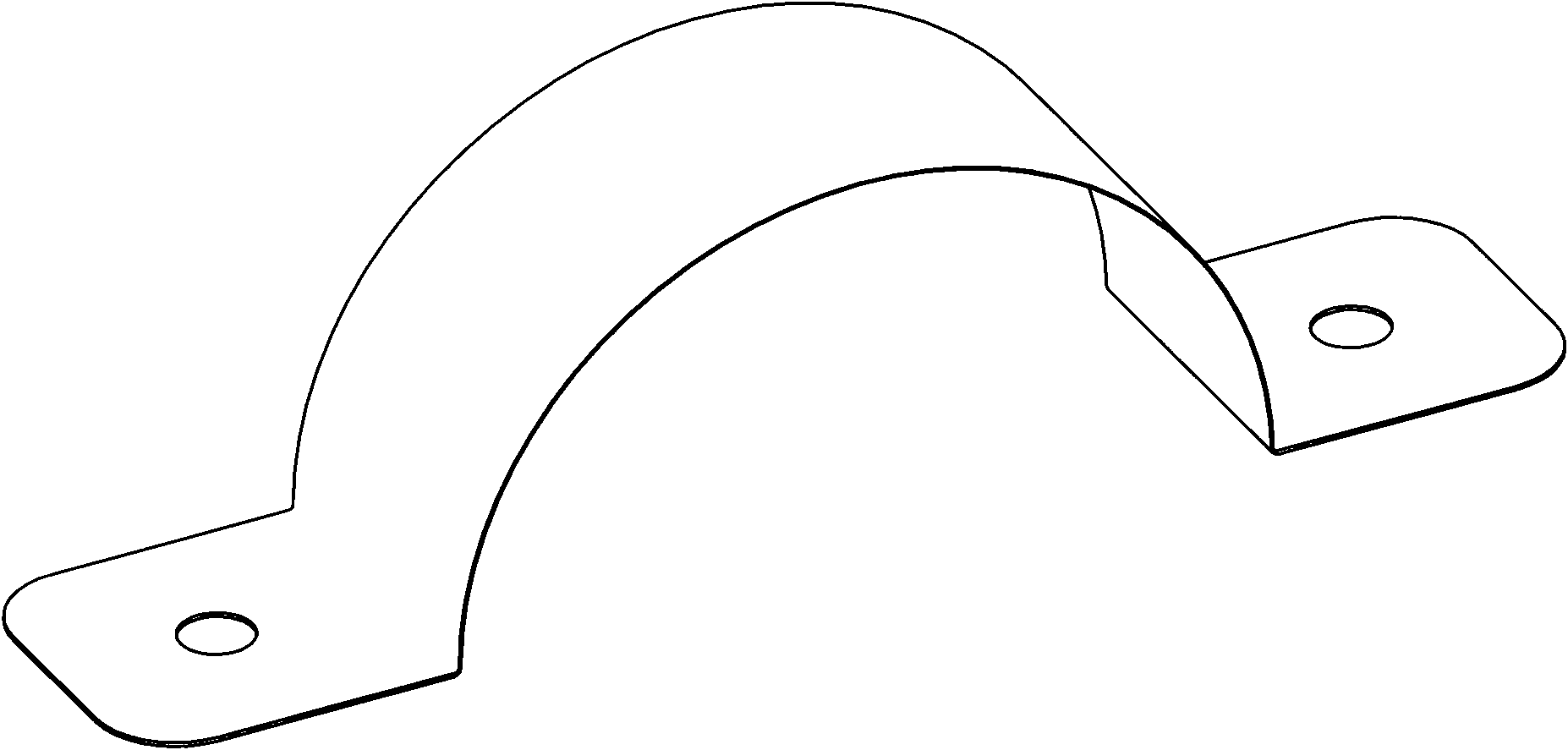
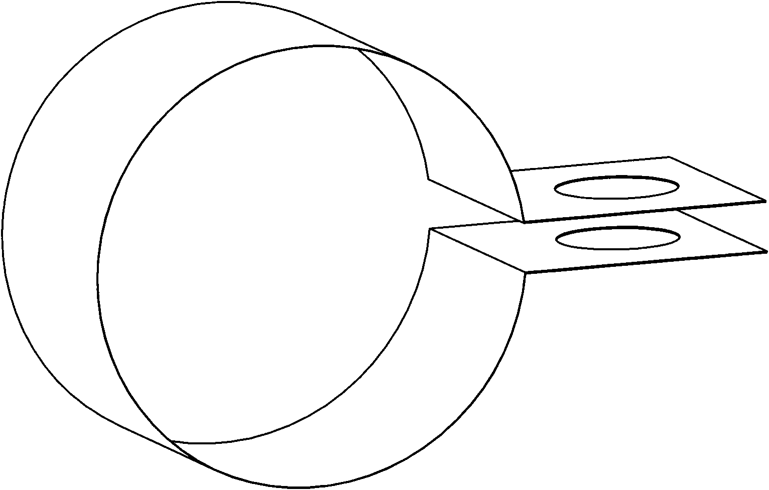
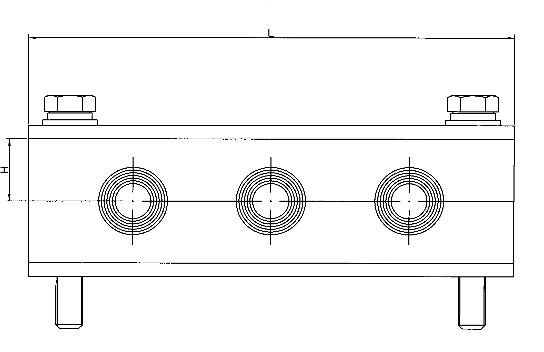
[0027] The present invention will be further described below in conjunction with the accompanying drawings. Such as Figure 1-5 As shown, a cable clamp includes an upper splint 1, a lower splint 2, an upper clamp 3, a lower clamp 4, a protective rubber ring 5 and a fixing bolt 6, and the upper splint 1, the lower splint 2, the upper clamp The two ends of the block 3 and the lower clamping block 4 are provided with fixing holes, and the bottom of the upper clamping block 3 and the upper part of the lower clamping block 4 are respectively processed with transverse semi-cylindrical grooves corresponding in position and in the same number. The clamping plate 1, the upper clamping block 3, the lower clamping block 4 and the lower clamping plate 2 are connected sequentially from top to bottom by fixing bolts 6, and the protective rubber ring 5 is installed in the round hole between the upper clamping block 3 and the lower clamping block 4 Middle; the upper clamping plate 1 and the ...


PUM


Abstract

The invention discloses a cable fixing clamp, comprising an upper clamping plate, a lower clamping plate, an upper clamping block, a lower clamping block, a protection rubber ring, and a fixing bolt. The lower part of the upper clamping block and the upper part of the lower clamping block are respectively provided with transverse semi-cylindrical slots at corresponding positions and with same quantity. The upper clamping plate, the upper clamping block, the lower clamping block and the lower clamping plate are connected in sequence from top to bottom through the fixing bolt. The protection rubber ring is arranged in a round hole between the upper clamping block and the lower clamping block, the upper clamping plate and the lower clamping plate are stainless steel plates, and the upper clamping block and the lower clamping block are DMC plastic blocks. The protection rubber ring consists of a plurality of layers of rubber rings. The upper clamping block and the lower clamping block are made of the DMC material with convenient processing, and the two clamping blocks can be prolonged according to the number of the cables needing to be fixed, thereby achieving the fixing of a plurality of cables. The fixing clamp of the invention can adapt to different cables through increasing or reducing the number of the protection rubber rings, thereby enhancing the installation efficiency.

Description

technical field [0001] The invention relates to an auxiliary part of electrical equipment, in particular to a cable fixing clip. Background technique [0002] Electrical equipment cables need to be fixed on walls or other cabinets during the laying process to prevent the cables from falling off and rubbing during long-term use, causing damage to the cables and avoiding short-circuit accidents. [0003] If the cable needs to be laid on a plane, you can use the following methods: figure 1 The structure shown is fixed, the middle semi-circle is the tight position of the cable, and there are round holes at both ends, which are fixed on the wall through screws. This structure is made of stainless steel or iron, in order to prevent the metal from wearing and tearing the cable The insulating layer needs to add a protective layer between the clamp and the cable. If it is not laid on a flat surface, you can also use such as figure 2 In the circular structure shown, the cable pass...

Claims


Application Information

Patent Timeline
Patent Type & Authority Applications(China)
IPC IPC(8): H02G3/32H02G3/30
Inventor 孔东晓戴碧君张可飞
Owner CHINA CNR LIMITED DALIAN ELECTRIC TRACTION R&D CENT
Why Eureka
Try Eureka