Engine air valve locking plate pressure head

A technology of engine valves and pressure heads, which is applied in the field of fixtures and fixtures, can solve problems such as force skewing of locking pieces, prolonging assembly time, and insufficient pressing of locking pieces, so as to prevent free swing, improve assembly efficiency, and be easy to press and fit in place Effect

Inactive Publication Date: 2011-03-09
力帆科技(集团)股份有限公司
View PDF4 Cites 8 Cited by
  • Summary
  • Abstract
  • Description
  • Claims
  • Application Information

AI Technical Summary

Problems solved by technology

The disadvantage of this press-fitting method is that the free swing of the valve spring on the cylinder head is relatively large, resulting in inaccurate positioning of the axis line of the valve stem, spring upper seat and pressure head during press-fitting, which increases the difficulty of assembly and easily causes If the locking piece is not pressed properly, it often happens that the locking piece pops out during pressing, or the locking piece is stressed and skewed during the pressing process, resulting in the failure to complete the pressing. On the one hand, the assembly time is prolonged, and the efficiency of pressing is low. On the one hand, it increases the workload of workers and requires higher proficiency of workers
In addition, during the pressing process, the guide positioning shaft in the indenter is prone to jump, which will also affect the efficiency and accuracy of locking plate pressing

Method used


Image

  • Engine air valve locking plate pressure head
  • Engine air valve locking plate pressure head
  • Engine air valve locking plate pressure head

Examples


Embodiment Construction

[0018] Below in conjunction with accompanying drawing and embodiment the present invention will be further described:

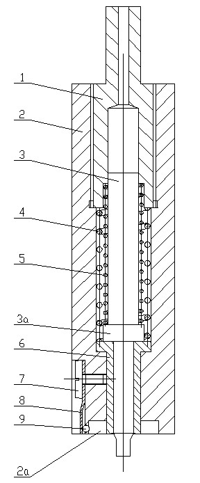
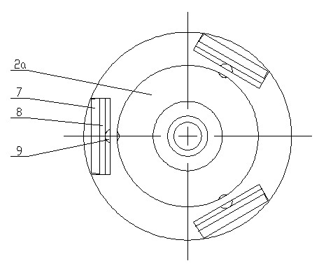
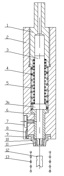
[0019] Such as figure 1 , figure 2 As shown, the present invention is made of guide screw plug 1, outer pressure head 2, guide positioning shaft 3, inner pressure head spring 4, positioning shaft spring 5, inner pressure head 6, bolt 7, reed 8 and steel ball 9, wherein The outer ram 2 is provided with a stepped inner hole along the direction of its axis, the upper inner hole of the outer ram 2 is a threaded section, the lower part of the guide screw plug 1 is put into the upper inner hole of the outer ram 2, through Threaded connections are held together. The top of the guide screw plug 1 is circular or square, which is compatible with the assembly hole of the lifting shaft of the press. A positioning groove 2a is provided in the middle of the bottom surface of the external pressure head 2, and an internal pressure head 6 is installed in the inner hole at...


PUM


Abstract

The invention discloses an engine air valve locking plate pressure head. A guide positioning shaft, an inner pressure head spring and a positioning shaft spring are arranged in an outer pressure head; a guide screw plug is arranged in an inner hole on the upper part of the outer pressure head, an inner pressure head is arranged in an inner hole on the lower part of the outer pressure head, and the bottom surface of the outer pressure head is provided with a positioning groove; and the peripheral wall of the positioning groove is provided with at least two positioning holes distributed uniformly according to the circumference, a steel ball is arranged in each positioning hole, each steel ball is provided with a reed, the upper part of the reed is fixed with the outer pressure head, and the lower part of the reed is pressed on the corresponding steel bal so that the small part of ball body of the steel ball is positioned in the positioning groove. The engine air valve locking plate pressure head has the advantages of simple operation, low labor intensity of workers and high work efficiency, and is not easy to damage an air valve, an air valve locking plate and an upper spring seat; and the upper spring seat and an air valve rod are positioned more accurately, and the locking plate is pressed in place more easily, so the locking plate is effectively prevented from falling in the running process of an engine, the locking plate is not popped up or inclined, and the assembly efficiency is improved.

Description

technical field [0001] The invention belongs to the technical field of fixtures, and in particular relates to a pressure head for an engine valve lock plate, which is used for pressing the valve lock plate into the valve and spring upper seat. Background technique [0002] During the engine assembly process, installing the valve lock plate is a very important link. At present, the valve locking plate assembly method adopted by various engine manufacturers is: the locking plate is installed in the spring upper seat, then placed on the valve spring, and pressed by a press. The disadvantage of this press-fitting method is that the free swing of the valve spring on the cylinder head is relatively large, resulting in inaccurate positioning of the axis line of the valve stem, spring upper seat and pressure head during press-fitting, which increases the difficulty of assembly and easily causes If the locking piece is not pressed properly, it often happens that the locking piec...

Claims


Application Information

Patent Timeline
Patent Type & Authority Applications(China)
IPC IPC(8): B23P19/02
Inventor 王忠信李中友
Owner 力帆科技(集团)股份有限公司
Why Eureka
Try Eureka