Ceramic tile splitting machine

A slitting machine and ceramic tile technology, applied in the direction of stone processing tools, manufacturing tools, stone processing equipment, etc., can solve problems such as difficult to ensure high accuracy of manufacturing and installation, large manpower and material costs, and achieve manpower saving and manufacturing The effect of low cost and accurate vertical conveying direction

Active Publication Date: 2011-03-09
FOSHAN YONGSHENGDA MACHINERY
View PDF5 Cites 6 Cited by
  • Summary
  • Abstract
  • Description
  • Claims
  • Application Information

AI Technical Summary

Problems solved by technology

[0002] Existing tile cutting machine, as disclosed in patent 200520057706.8, includes a frame, a tile conveying belt device arranged on the frame, a cutting knife fixed on the belt of the tile conveying belt device arranged on the frame The rotating shaft mechanism of the disk, the lifting mechanism arranged under the rotating shaft mechanism, the lifting mechanism includes lifting platforms located at both ends of the rotating shaft mechanism, and a power mechanism that drives the two lifting platforms to rise and fall synchronously. Although this kind of device solves the problems it needs to solve, but, Determined by the nature of product processing, the lifting table needs to be accurately linked, and it is necessary to ensure that the rotating shaft of the rotating shaft mechanism mounted on the lifting table and fixed with a cutting cutter is accurately perpendicular to the conveying direction of the conveyor belt. Due to the above-mentioned patented technology The components are manufactured separately and then assembled together, so it is difficult to ensure the high accuracy of manufacturing and installation, even if the above-mentioned accuracy can be achieved, it will cost a lot of manpower and materials

Method used


Image

  • Ceramic tile splitting machine
  • Ceramic tile splitting machine
  • Ceramic tile splitting machine

Examples


Embodiment 1

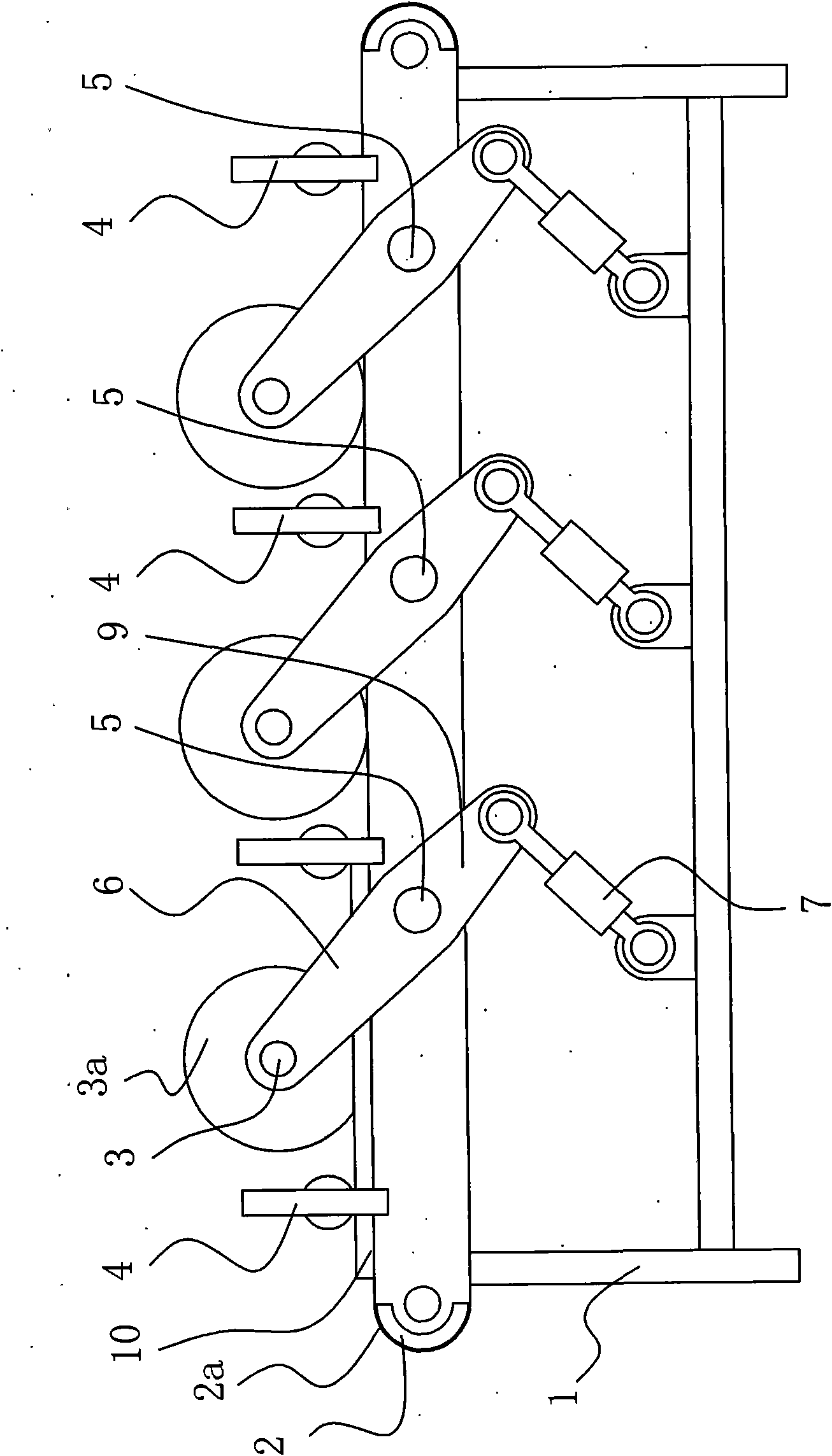
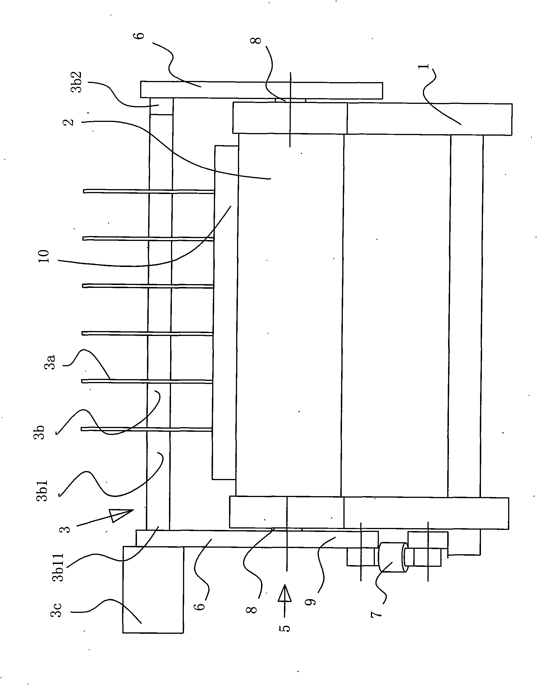
[0011] Embodiment 1: as figure 1 , 2 As shown, the present invention comprises a frame 1, a tile conveying belt device 2 arranged on the frame 1, a rotating shaft fixed on the belt 2a of the ceramic tile conveying belt device 2 on the frame 1 and fixed with a cutting cutter head 3a Mechanism 3, the brick pressing mechanism 4 arranged on the tile conveying belt device 2, the lifting mechanism 5 arranged under the rotating shaft mechanism 3, the special feature of which is that the lifting mechanism 5 includes a frame that is rotatably arranged on both sides of the tile conveying belt device 2 The swing arm 6 on 1, the power mechanism 7 that drives the swing arm 6 to swing, the rotating shaft mechanism 3 is fixed on the swing arm 6 on both sides of the frame 1, the rotating shaft mechanism 3 includes the rotating shaft 3b that is arranged on the swing arm 6, and is fixed on Drive the motor 3c that rotating shaft 3b rotates at a high speed on the swing arm 6, and cutting disc 3a...

Embodiment 2

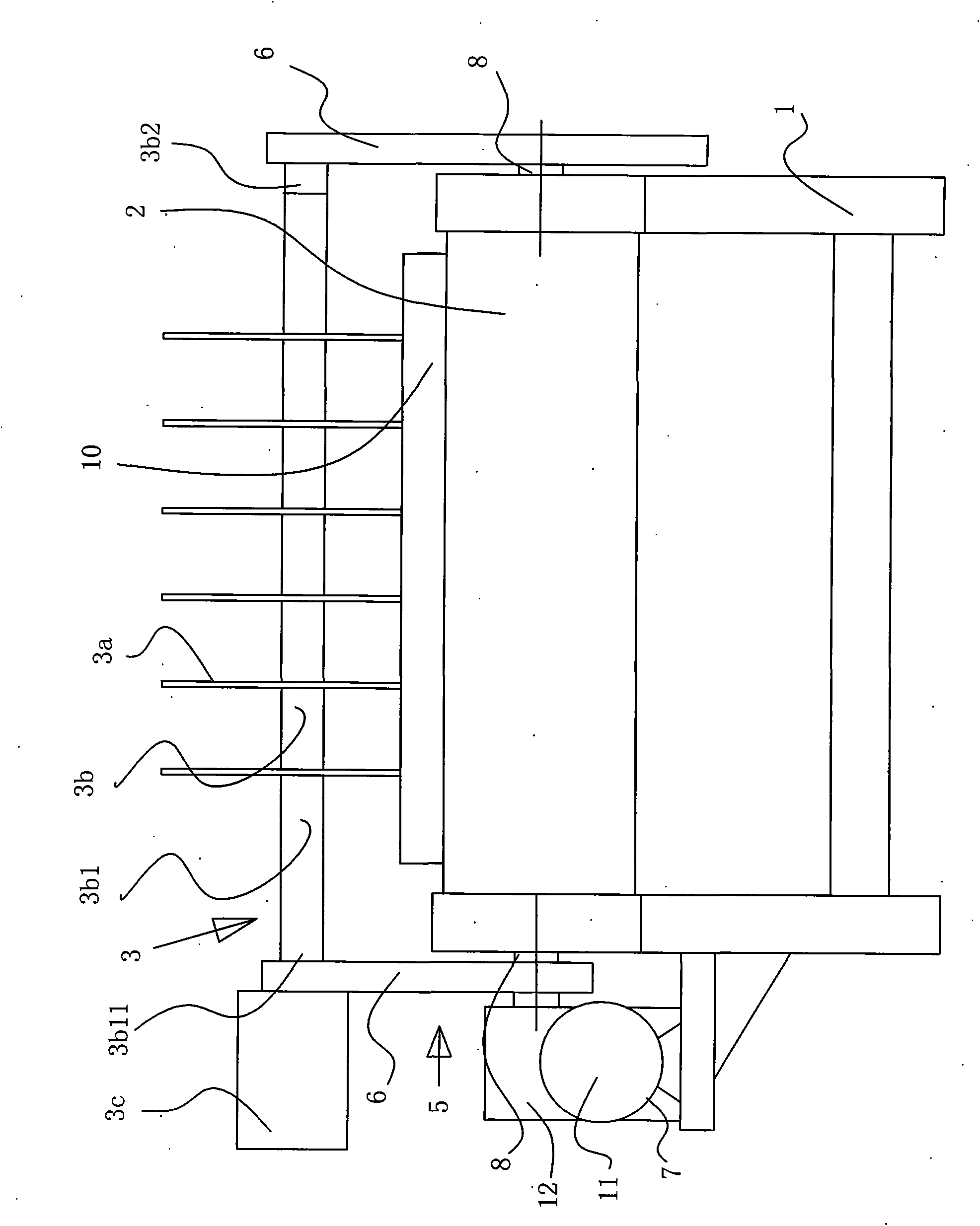
[0012] Embodiment 2: as figure 1 , 3 Shown, present embodiment is on the basis of embodiment 1, and swing arm 6 is arranged on the side of frame 1 by the rotation of shaft 8, and power mechanism 7 is the transmission device 12 that has motor 11, and the transmission device with motor 11 12 is connected with the shaft 8, the speed change device 12 adopts a worm gear type speed change device, and the motor 11 adopts a stepper motor, so that the swing arm is adjusted through the stepping transmission of the stepper motor 11 and the speed change of the worm gear type speed change device 12 The distance between the cutting disc 3a of the rotating shaft mechanism 3 on the 6 and the conveyed tiles 10 on the tile conveying belt device 2.


PUM


Abstract

The invention relates to a ceramic tile splitting machine. The ceramic tile splitting machine comprises a framework, a ceramic tile conveying belt device arranged on the framework, a shaft mechanism which is fixed with a cutter disc, is arranged on the framework and is positioned on the belt of the ceramic tile conveying belt device, a tile press mechanism arranged on the ceramic tile conveying belt device and an elevating mechanism arranged below the shaft mechanism. The ceramic tile splitting machine is characterized in that the elevating mechanism comprises swing arms rotatably arranged on the framework at both sides of the ceramic tile conveying belt device and a power mechanism driving the swing arms to swing, and the shaft mechanism is fixed on the swing arms at both sides of the framework. Compared with the prior art, the invention can easily realize that the shaft of the shaft mechanism fixed with a cutter disc is exactly perpendicular to the conveying direction of the conveying belt and every position of the shaft of the shaft mechanism can be synchronously elevated. Besides, the invention has the advantages of labor saving and low manufacturing cost.

Description

Technical field: [0001] The invention relates to a ceramic tile processing device. Background technique: [0002] Existing tile cutting machine, as disclosed in patent 200520057706.8, includes a frame, a tile conveying belt device arranged on the frame, a cutting knife fixed on the belt of the tile conveying belt device arranged on the frame The rotating shaft mechanism of the disk, the lifting mechanism arranged under the rotating shaft mechanism, the lifting mechanism includes lifting platforms located at both ends of the rotating shaft mechanism, and a power mechanism that drives the two lifting platforms to rise and fall synchronously. Although this kind of device solves the problems it needs to solve, but, Determined by the nature of product processing, the lifting table needs to be accurately linked, and it is necessary to ensure that the rotating shaft of the rotating shaft mechanism mounted on the lifting table and fixed with a cutting cutter is accurately perpendicu...

Claims


Application Information

Patent Timeline
Patent Type & Authority Applications(China)
IPC IPC(8): B28D1/24
Inventor 刘永钦
Owner FOSHAN YONGSHENGDA MACHINERY
Why Eureka
Try Eureka