
Fluctuating surface pre-stack time migration method and device based on common aperture surface

A pre-stack time migration and undulating surface technology, applied in seismic signal processing and other directions, can solve the problem that pre-stack time migration technology cannot be accurately applied to the surface

Inactive Publication Date: 2011-03-09
BEIJING GEOSTAR SCI & TECH
View PDF2 Cites 17 Cited by
  • Summary
  • Abstract
  • Description
  • Claims
  • Application Information

AI Technical Summary

Problems solved by technology

[0005] The present invention provides a pre-stack time migration method and equipment based on a common aperture surface, which is used to solve the defect in the prior art that the pre-stack time migration technology cannot be accurately applied due to the surface height difference, so as to achieve higher precision imaging geological form

Method used


Image

  • Fluctuating surface pre-stack time migration method and device based on common aperture surface
  • Fluctuating surface pre-stack time migration method and device based on common aperture surface
  • Fluctuating surface pre-stack time migration method and device based on common aperture surface

Examples


Embodiment 1

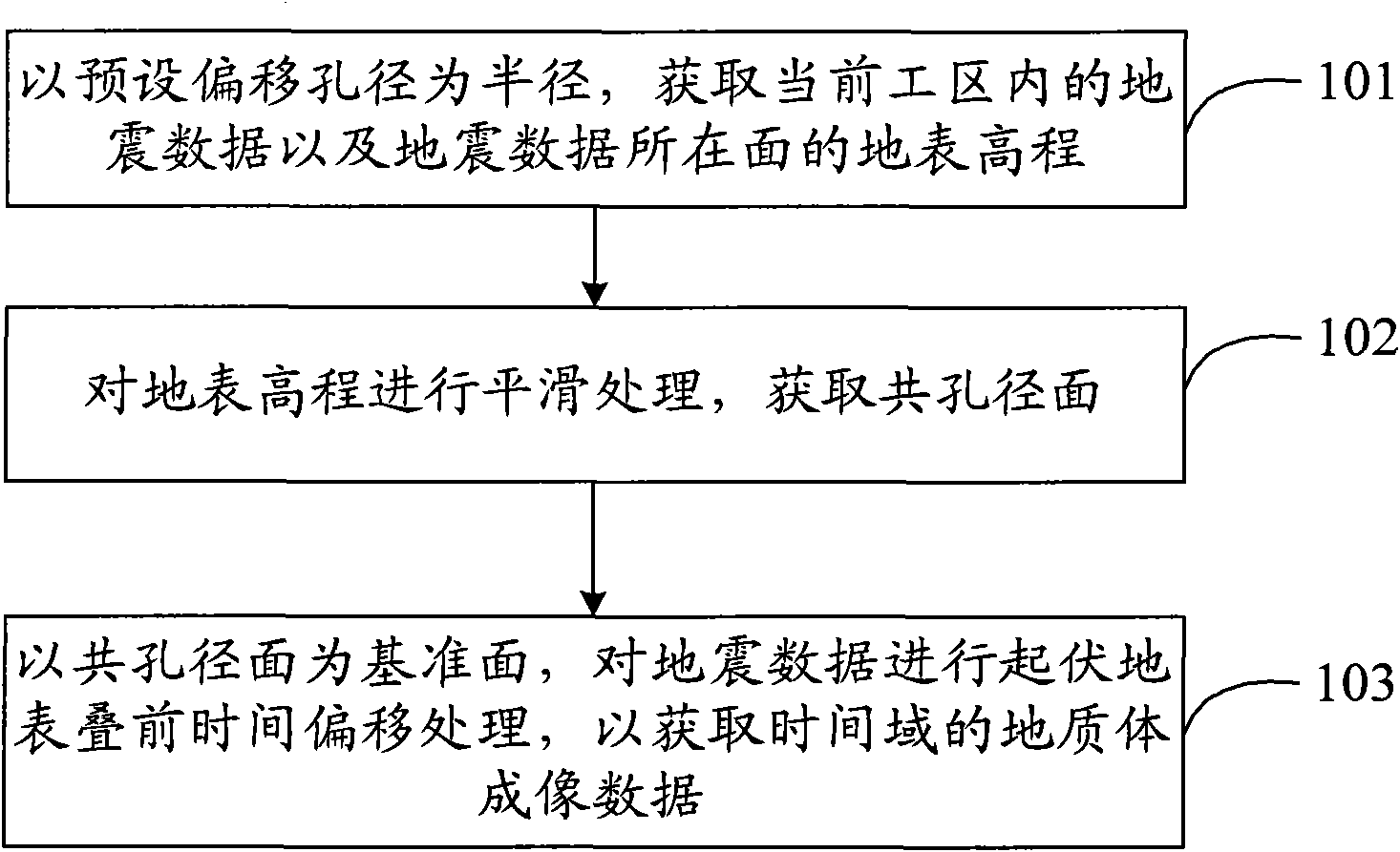
[0024] figure 1 A flow chart of the prestack time migration method based on the common aperture surface for the undulating surface provided by Embodiment 1 of the present invention. Such as figure 1 As shown, the pre-stack time migration method for the undulating surface of this embodiment includes:

[0025] Step 101, taking the preset offset aperture as the radius, acquiring the seismic data in the current work area and the surface elevation of the plane where the seismic data is located;

[0026] Wherein, the offset aperture refers to the coordinate range of input data (ie, seismic data) that contributes to a certain imaging output. The preset offset aperture in this embodiment selects the maximum offset aperture, which can effectively contain all contributing input data. The working area mentioned in this embodiment also refers to the maximum range of the coordinates of the seismic data to be processed at present. In this embodiment, the way to acquire the surface eleva...

Embodiment 2

[0053] Figure 5 A schematic structural diagram of a prestack migration device for undulating terrain based on a common aperture surface provided in Embodiment 2 of the present invention. Such as Figure 5 As shown, the device in this embodiment includes: a first acquisition module 51 , a second acquisition module 52 and a processing module 53 .

[0054] Wherein, when using the equipment of this embodiment to perform pre-stack time migration processing, the work area to be processed is usually selected, specifically referring to the coordinate range of the seismic data to be processed. The first acquisition module 51 is configured to acquire the seismic data in the current work area and the surface elevation of the plane where the seismic data is located, using the preset offset aperture as the radius. Among them, the preset offset aperture can artificially select the maximum offset aperture according to the coordinate range of the seismic data, so as to effectively contain ...


PUM


Abstract

The invention provides a fluctuating surface pre-stack time migration method and device based on common aperture surface; the method comprises: taking the presupposed migration aperture as semidiameter, obtaining seismic data in the current work area and a surface height of a surface where the seismic data lies; smoothing the surface height so as to obtain a common aperture surface; taking the common aperture surface as a reference surface and performing the fluctuating surface pre-stack time migration treatment on the seismic data so as to obtain geologic body image data of time domain. The technical scheme performs the pre-stack time migration by taking the common aperture surface that is relatively smooth and rather small in height as the reference surface, thereby being capable of overcoming the defect of structuring wrong geological shape by the pre-stack time migration due to big difference of the height of the floating reference surface in the prior art so as to construct the geological shape with higher precision.

Description

technical field [0001] The invention relates to seismic data imaging technology, in particular to a pre-stack time migration method and equipment for undulating surface based on a common aperture surface. Background technique [0002] Prestack migration is a seismic data processing technology proposed in the 1970s, which includes prestack time migration technology and prestack depth migration technology. Among them, the Kirchhoff pre-stack time migration technology has the characteristics of strong adaptability to the velocity model, stable calculation, and direct-to-target calculation, and has become a routine process for seismic data processing. Especially for some mountainous areas, the underground geological structure is complex, the surface elevation changes drastically, and depth velocity modeling is difficult. However, the pre-stack time migration technology can significantly improve the imaging accuracy, so the pre-stack time migration technology is widely used. [...

Claims


Application Information

Patent Timeline
IPC IPC(8): G01V1/28G01V1/36
Inventor 刘国峰
Owner BEIJING GEOSTAR SCI & TECH
Learn More