Efficient screening distributor

A distributing device and screening technology, which is applied in the fields of filtering and sieving, solid separation, chemical instruments and methods, etc., can solve the problems of uneven distribution, material blockage, no iron removal parts, etc., and achieve low operating cost, reasonable structure, and easy maintenance. The effect of easy maintenance

Active Publication Date: 2011-03-16
SICHUAN ZHONGMENG ELECTRIC POWER EQUIP MFG CO LTD
View PDF6 Cites 8 Cited by
  • Summary
  • Abstract
  • Description
  • Claims
  • Application Information

AI Technical Summary

Problems solved by technology

[0006] The purpose of the present invention is to overcome the shortcomings of the prior art and provide a high-efficiency sieve distributor to solve the problems of low screening efficiency, uneven distribution, poor fluidity o

Method used


Image

  • Efficient screening distributor
  • Efficient screening distributor
  • Efficient screening distributor

Examples


Embodiment 1

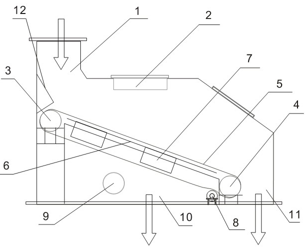
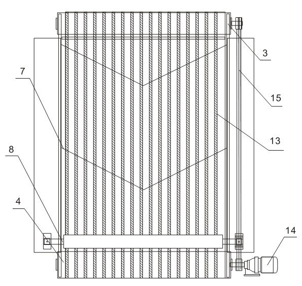
[0022] [Example 1]: as figure 1 and figure 2 , a high-efficiency screen distributor, which includes a feed port 1, an upper roller 3, a lower roller 4, a string screen surface 5, a fixed string screen 6, a coal scraping device 7, a tensioning device 8, a distribution plate 12 and The filter rope 13 and the distribution plate 12 are arranged on the inner wall below the feed port 1, the string screen surface 5 is composed of several filter ropes 13 arranged in parallel in the longitudinal direction consistent with the movement direction, and the string screen surface 5 surrounds the upper roller 3 , On the lower roller 4, two upper and lower sieve surfaces that are connected end to end and can be rotated are formed. The fixed string sieve 6 is also composed of several filter ropes arranged in parallel longitudinally, located below the upper sieve surface of the string sieve surface 5, The coal scraping device 7 is located between the upper and lower screen surfaces of the stri...

Embodiment 2

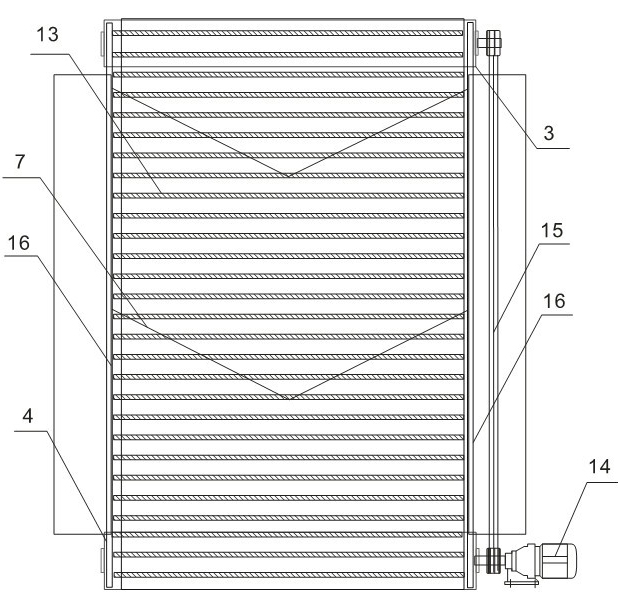
[0036] [Example 2]: as figure 1 and image 3 , a high-efficiency screen distributor, which includes a feed port 1, an upper roller 3, a lower roller 4, a string screen surface 5, a fixed string screen 6, a coal scraping device 7, a tensioning device 8, a distribution plate 12 and The filter rope 13 and the distribution plate 12 are arranged on the inner wall below the feed port 1, and the string screen surface 5 is composed of several filter ropes 13 arranged in parallel horizontally or perpendicularly to the direction of motion or at a certain angle, and the string screen surface 5 is surrounded by On the upper roller 3 and the lower roller 4, two upper and lower sieve surfaces connected end to end and can be rotated are formed. The fixed string sieve 6 is also composed of several filter ropes arranged in parallel, and is located on the upper sieve surface of the string sieve surface 5. Below, the coal scraping device 7 is located between the upper and lower screen surfaces ...


PUM


Abstract

The invention discloses an efficient screening distributor which comprises a feed inlet (1), an upper rolling shaft (3), a lower rolling shaft (4), a piano wire screen surface (5), a fixed piano wire screen (6), a coal wiper (7), a tension device (8), a distribution plate (12), a motor (14) and a transmission device (15), wherein, the piano wire screen surface (5) is composed of a plurality of filtering ropes (13) arranged in parallel, and the piano wire screen surface (5) surrounds the upper rolling shaft (3) and the lower rolling shaft (4) to form an upper screen surface and a lower screen surface which are connected end to end and can perform gyratory motion; and the fixed piano wire screen (6) is positioned below the upper screen surface of the piano wire screen surfaces (5). The efficient screening distributor solves the problems of the existing screening distributor, such as unadjustable particle size, unadjustable tension of the screen surfaces, channel blockage caused by materials, difficult coal unloading, low screening efficiency, uneven distribution, failure in removal of iron castings from the materials and the like; and the efficient screening distributor has the advantages of rational structure, low operating cost and the like, and is convenient to maintain and overhaul.

Description

technical field [0001] The invention relates to a high-efficiency screen distributor. Background technique [0002] The fuel of circulating fluidized bed boilers in thermal power plants is coal gangue with a certain particle size. Most of the material particle sizes in the incoming coal from coal mines do not need repeated crushing. Generally, the proportion of about 35-75% of the material is the qualified particle size. If this part of the qualified particle size is not screened out by the sieve distribution equipment, it will cause several negative effects on the subsequent crusher: (1) The crusher will run overloaded for a long time, the power consumption will increase, and the service life of the motor will be shortened ; (2) The large amount of over-crushing directly affects the combustion efficiency of the boiler; (3) The internal wear of the crusher is intensified, and the service life of the hammer head is greatly shortened; (4) The material falls into the crusher i...

Claims


Application Information

Patent Timeline
IPC IPC(8): B07B1/28B07B1/46
Inventor 马琳
Owner SICHUAN ZHONGMENG ELECTRIC POWER EQUIP MFG CO LTD
Why Eureka
Try Eureka