Safety protection device for piano wire

A technology of safety protection device and steel wire, applied in wellbore/well components, measurement, earth-moving drilling, etc., can solve problems such as economic loss, personnel poisoning, oil and gas leakage, etc., to avoid oil and gas leakage, prevent falling into the bottom of the well, The effect of reducing friction

Active Publication Date: 2020-09-15
PETROCHINA CO LTD
View PDF4 Cites 2 Cited by
  • Summary
  • Abstract
  • Description
  • Claims
  • Application Information

AI Technical Summary

Problems solved by technology

[0003] In the related technology, the well test steel wire is used as the carrier for connecting the test equipment, and its diameter is usually only 2.33mm. During the hoisting process of the well test steel wire, wax, mud, mudstone, sand, oil and water and other sundries tend to adhere to the well test steel wire. When the well test wire is moved out of the high-pressure wellbore and returned to the atmospheric pressure state and then retracted to the wire test drawworks, the well test wire with debris and the top seal of the blowout pipe will rub against each other, which may cause the well test wire to be pulled. The stress increases and the fracture occurs, which in turn causes the test equipment and well test steel wire to fall into the bottom of the well, causing huge economic losses
In addition, a dynamic sealing surface will be formed between the well test wire with debris and the top seal of the blowout preventer. Since the debris is not smooth and flat, the seal is not tight, so there will be oil and gas leakage from the wellbore to the surroundings of the well site. potential safety hazards, especially if the oil and gas contain substances such as hydrogen sulfide, there will be a risk of personnel poisoning

Method used


Image

  • Safety protection device for piano wire

Examples


Embodiment Construction

[0022] In order to make the object, technical solution and advantages of the present invention clearer, the implementation manner of the present invention will be further described in detail below in conjunction with the accompanying drawings.

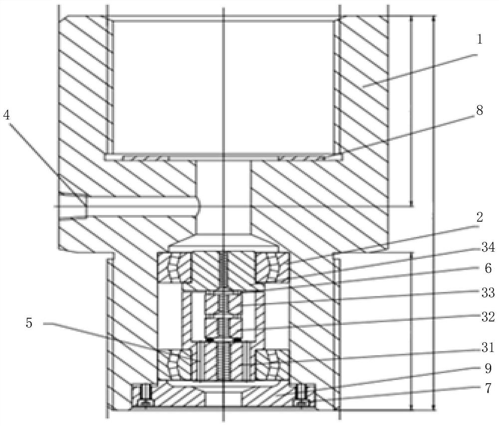
[0023] figure 1 It is a structural schematic diagram of a well testing steel wire safety protection device provided by an embodiment of the present invention. see figure 1 , the device includes: a blowout preventer connection section 1, a bearing support section 2, a rotating step-by-step decontamination section 3, a liquid injection section 4 and a dirt chip removal hole 5.

[0024] Among them, the upper end of the blowout preventer connection section 1 is connected to the blowout preventer, the lower end is connected to the wellhead flange of the wellbore gas tree, the bearing support section 2, the rotating step-by-step decontamination section 3, the liquid injection section 4 and the dirt removal hole 5 They are all cylindrical s...


PUM


Abstract

The invention discloses a safety protection device for a piano wire. The safety protection device comprises a blowout prevention pipe connection segment, a bearing support segment, a rotary stepwise decontamination segment, a liquid injection segment and a dirt drain hole, wherein the upper end of the blowout prevention pipe connection segment is connected with a blowout prevention pipe; the lowerend of the blowout prevention pipe connection segment is connected with a shaft gas production tree shaft mouth flange; the five parts of the safety protection device are of cylindrical structures, and are all arranged inside the blowout prevention pipe connection segment; the blowout prevention pipe connection segment, the bearing support segment and the rotary stepwise decontamination segment are sleeved sequentially from outside to inside; the rotary stepwise decontamination segment comprises a first rotating body, a second rotating body, a third rotating body and a fourth rotating body which are connected sequentially from bottom to top, and is used for removing dirt from the piano wire stepwise, and draining the removed dirt through the dirt drain hole; and the liquid injection segment is arranged on the blowout prevention pipe connection segment transversely, and is used for lubricating and cooling the piano wire after being injected with liquid. The safety protection device caneffectively remove sundries attached to the piano wire, and cool the piano wire.

Description

technical field [0001] The invention relates to the field of well testing and testing operations of oil and gas wells, in particular to a safety protection device for well testing steel wires. Background technique [0002] In the process of oil and gas field development, it is often necessary to understand the performance of oil and gas reservoirs through well testing, such as obtaining test data to evaluate the production performance of oil and gas wells, studying various physical parameters, production capacity, And the connectivity among oil layer, gas layer and water layer etc. Among them, the well test test operation mainly tests formation pressure, temperature and flow rate changes, etc. Specifically, a steel wire well test winch is usually used to operate the test equipment (electronic pressure gauge) into the high-pressure wellbore for testing. [0003] In the related technology, the well test steel wire is used as the carrier for connecting the test equipment, and ...

Claims


Application Information

Patent Timeline
Patent Type & Authority Applications(China)
IPC IPC(8): E21B47/00E21B33/08
CPCE21B47/00E21B33/08
Inventor 阮开贵吴应辉黄平易浩鄢传悟陈维志彭通
Owner PETROCHINA CO LTD
Why Eureka
Try Eureka