Clamp

A clamp and clip technology, applied in the direction of clamps, manufacturing tools, etc., can solve the problems of inconvenient operation, labor-saving, and difficult to realize convenient disassembly and assembly, and achieve the effect of compact structure, convenient operation, convenient disassembly and installation.

Inactive Publication Date: 2012-07-25
HANGZHOU UNITED ELECTRIC MFG CO LTD
View PDF0 Cites 1 Cited by
  • Summary
  • Abstract
  • Description
  • Claims
  • Application Information

AI Technical Summary

Problems solved by technology

[0002] The existing fixture includes a fixed clip body, a movable clip body, a guide rod, and a booster handle. The guide rod is equipped with a locking clip and a booster clip, and the booster clip is driven by the booster handle to pass through the fixed The guide rod on the clamp body moves to change the distance between the fixed clamp body and the movable clamp body to achieve clamping. However, the force handle of the existing structure clamp is often connected to the fixed clamp body through a revolving pin. The feed distance and clamping force generated by the guide rod by holding the booster handle are basically the same, and it is difficult to meet the requirements of large-step feed of the guide rod in neutral and greater clamping force when clamping.
[0003] In addition, the movable clamp body of the existing clamp is usually fixed on the guide rod, and the positional relationship between the movable clamp body and the fixed clamp body cannot be changed, so the clamp only has the function of clamping or supporting
In order to make the clamp have both clamping and supporting functions, although the movable clamp body can be movably connected to the guide rod, it is difficult to ensure the bonding strength and sufficient clamping force of the movable clamp body and guide rod in the existing connection method , it is also difficult to achieve convenient disassembly
[0004] In addition, when the clamp clamps the object through the fixed clamp body and the movable clamp body, the locking clip locks the guide rod, and when releasing, it is necessary to release the locking of the locking clip to the guide rod, and the prior art usually uses Auxiliary tools other than the fixture are used to pry the locking clip to leave, which is inconvenient to operate and labor-saving

Method used


Image

  • Clamp
  • Clamp
  • Clamp

Examples


Embodiment Construction

[0020] The present invention will be further described below in conjunction with accompanying drawing of description:

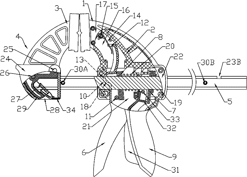
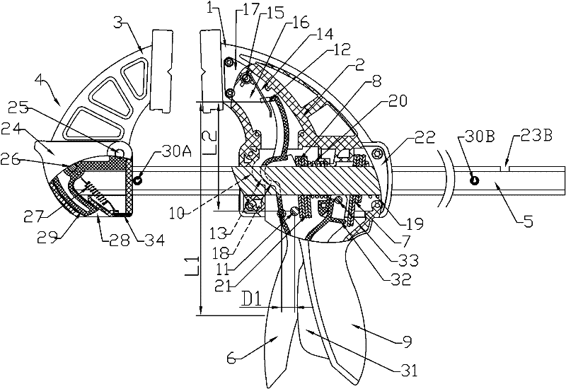
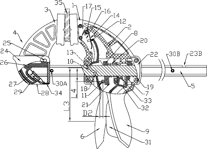
[0021] Such as figure 1 As shown, the fixture of the present invention includes a fixed clamp body 2 with a fixed chuck 1, a movable clamp body 4 with a movable chuck 3, a guide rod 5, and a force handle 6, and the guide rod 5 is penetrated on the fixed clamp body 2 , and configure the locking clip 7 and the force clip 8 for the guide rod 5, the movable clip body 4 is installed on one end of the guide rod 5 (the left end in the figure) and the fixed chuck 1 corresponds to the movable chuck 3, The fixed clip body 2 has a handle 9 extending toward the other end of the fixed chuck 1, and a fixed support portion 10. The booster handle 6 is provided corresponding to the handle 9. The booster handle 6 has a handle for pushing against and adding The force applying portion 11 of the force clip 8 (specifically, it may be a shaft installed on the force applying handle...


PUM


Abstract

The invention discloses a clamp, the existing clamp is difficult to meet the using requirements of leading a guide rod to realize big-step feeding in neutral gear and obtaining greater clamping force during clamping, a fixed clamp body of the clamp comprises a grab handle which extends to the end which is not fixed with a clamping head and a fixed supporting part, a force application handle is arranged by corresponding to the grab handle, and a force application part for pushing a force application clamping piece, a first fulcrum part which is farther away from the force application part and a second fulcrum part which is nearer to the force application part are arranged on the force application handle, wherein an elastic element is connected between the first fulcrum part and the fixed clamp body, and the second fulcrum part is arranged by corresponding to the fixed supporting part. The clamp can lead the force application handle to act by taking the first fulcrum part as the fulcrumin the neutral gear, thereby leading the force application part of the force application handle to obtain a greater amount of feeding and realizing fast feeding; and the clamp can further lead the force application handle to act by taking the second fulcrum part as the fulcrum during clamping, thereby leading the force application part of the force application handle to obtain the greater clamping force.

Description

technical field [0001] The invention relates to a clamp, in particular to a clamp which can make a guide rod advance in large steps when in neutral, and can obtain a relatively large clamping force when clamping. Background technique [0002] The existing fixture includes a fixed clip body, a movable clip body, a guide rod, and a booster handle. The guide rod is equipped with a locking clip and a booster clip, and the booster clip is driven by the booster handle to pass through the fixed The guide rod on the clamp body moves to change the distance between the fixed clamp body and the movable clamp body to achieve clamping. However, the force handle of the existing structure clamp is often connected to the fixed clamp body through a revolving pin. The feeding distance and clamping force generated by the guide rod by holding the booster handle are basically the same, which is difficult to meet the requirements of large-step feed of the guide rod in neutral and greater clamping...

Claims


Application Information

Patent Timeline
Patent Type & Authority Patents(China)
IPC IPC(8): B25B5/02B25B5/16
Inventor 仇建平
Owner HANGZHOU UNITED ELECTRIC MFG CO LTD
Why Eureka
Try Eureka