Cutting blade and cutting tool

A technology for cutting blades and blades, which is applied in the direction of milling cutters, manufacturing tools, metal processing equipment, etc., can solve the problems affecting the finishing process and uneven residual materials, so as to improve the quality, strengthen the strength and toughness of the blade tip, and reduce chipping risk effect

Active Publication Date: 2021-11-19
ZHUZHOU HUARUI PRECISION CUTTINGS TOOLS CO LTD
View PDF9 Cites 0 Cited by
  • Summary
  • Abstract
  • Description
  • Claims
  • Application Information

AI Technical Summary

Problems solved by technology

[0005] In the aerospace industry, it is often necessary to remove a large amount of material from titanium alloys, aluminum alloys and other materials, and these parts often have ribbed structures, and the verticality requirements of these parts are relatively high. Before finishing machining, especially The vertical wall needs to leave a uniform machining allowance to ensure that the finishing tool reduces vibration and avoid the rapid failure of the finishing tool. However, the existing cutting blade will leave uneven residual material when machining the vertical wall, which will affect the subsequent finishing. Processing

Method used


Image

  • Cutting blade and cutting tool
  • Cutting blade and cutting tool
  • Cutting blade and cutting tool

Examples


Embodiment 1

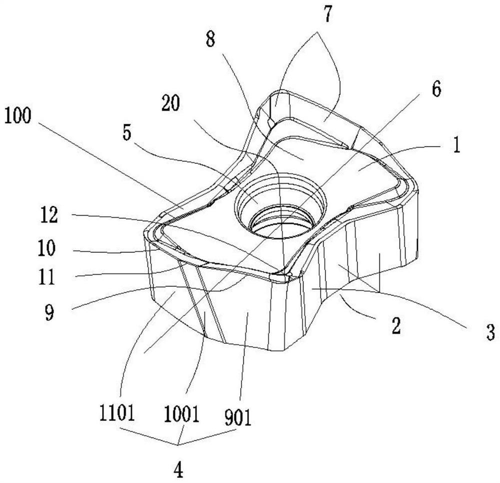
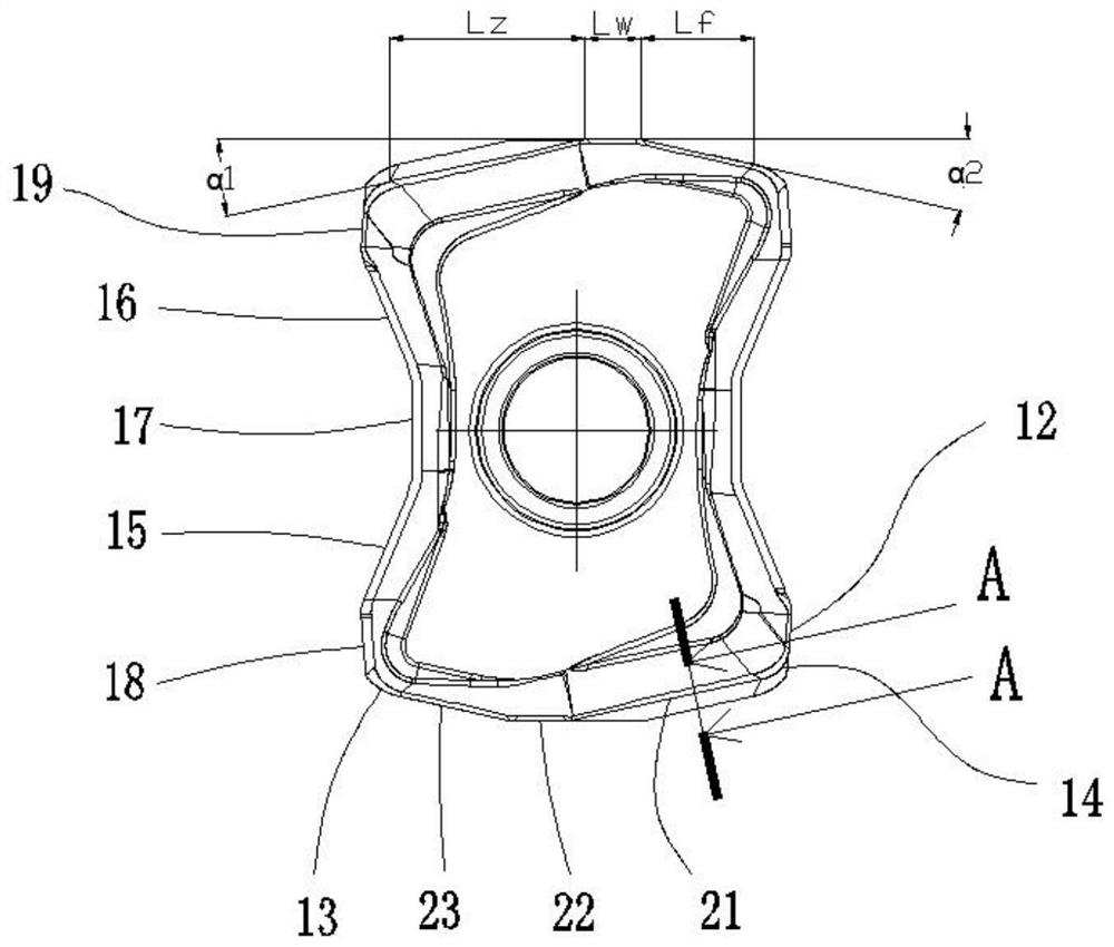
[0039] This embodiment adopts the method of plane milling, such as Figure 1-9 Shown is a cutting insert described in this embodiment, including a top face 1, a bottom face 2, a side face 3 and a relief face 4 to form a blade body 100, and the blade body 100 runs through the top face 1 and the bottom face 2. A screw hole 5 is provided, and the top surface 1 and the bottom surface are distributed rotationally symmetrically with the first central axis 6 set vertically to the screw hole 5; 8, the edge band where the rake face 7 intersects with the flank face 4 forms a cutting edge portion, and the cutting edge portion includes a main cutting edge 9, a minor cutting edge 10, a first wiper edge 11, and respectively The cutter face 4 forms the main cutting edge flank 901, the secondary cutting edge flank 1001 and the first wiper flank 1101, and the length of the main cutting edge 9 is greater than the length of the secondary cutting edge 10; the main cutting edge 9 and Minor cuttin...

Embodiment 2

[0052] Such as Figure 10 As shown, the difference between this embodiment and Embodiment 1 is that this embodiment adopts plunge milling. In the cutting process of this embodiment, the tool rotates at high speed along the direction shown in the figure, the workpiece 300 remains stationary, and the tool moves along Feed movement is performed in the direction shown by the arrow, and the cutting edge on the cutting blade participates in a cutting every time the tool rotates one circle. The vertical wall surface is smoothed until the workpiece 300 forms the desired processed surface 500; in the cutting process, if the cutting edge of the blade is worn or damaged and the processing cannot be continued, it is necessary to stop the processing and unscrew the tightening After changing the angle of the cutting blade with the fixing screw, reinstall it and use it.


PUM


Abstract

The invention discloses a cutting blade which comprises a blade body defined by a top face part, a bottom face part, a side face part and a rear tool face, and the blade body penetrates through the top surface part and the bottom surface part and is provided with a screw hole part. Each of the top surface part and the bottom surface part is composed of a front cutter surface and a mounting surface, a cutting edge part is formed by an edge band where the front cutter surface and the rear cutter surface intersect, the cutting edge part comprises a main cutting edge, an auxiliary cutting edge and a first sleeking edge, and the main cutting edge, the auxiliary cutting edge and the first sleeking edge form a main cutting edge rear cutter surface, an auxiliary cutting edge rear cutter surface and a first sleeking edge rear cutter surface respectively with the rear cutter surface; the main cutting edge is longer than the auxiliary cutting edge; and the cutting edge part further comprises a second sleeking edge, and the second sleeking edge is smoothly connected with the main cutting edge through a second arc section. The cutting blade has the advantages of larger cutting depth and larger feeding under the same blade width, and a vertical wall surface with higher quality can be formed in the processing of a rib structure.

Description

technical field [0001] The invention relates to the technical field of cutting blades, in particular to a cutting blade and a cutting tool. Background technique [0002] In metal cutting, milling is the most common processing method. Usually, the required processing parts are fixed on the machine tool table, and the high-speed rotating milling tool is used to move the tool on the surface of the part at a certain feed rate, and the desired machining results are obtained. The shape and characteristics of the required parts, among which, the feed rate of the tool determines the cutting efficiency of the tool. [0003] CN102036776B proposes a cutting insert solution: a cutting insert comprising an upper and a lower face opposite to each other, two longitudinal sides and two transverse sides connecting the upper and lower faces, the longitudinal sides are opposite to each other and connected to the upper perpendicular to the lower side, the lateral sides are opposite to each oth...

Claims


Application Information

Patent Timeline
Patent Type & Authority Applications(China)
IPC IPC(8): B23C5/20
CPCB23C5/202
Inventor 吴志龙陈胜男高江雄
Owner ZHUZHOU HUARUI PRECISION CUTTINGS TOOLS CO LTD
Why Eureka
Try Eureka