
A machine clip type thread turning tool

A thread turning tool and machine clip technology, which is applied in the direction of lathe tools, cutting blades, turning equipment, etc., can solve the problem of limiting cutting feed and cutting speed, small blade cutting reaction force, and small cutting feed and other problems, to achieve the effect of cleaning, fast cutting speed and large feed rate

Active Publication Date: 2018-11-30
NINGBO CHUANJINGYU MECHANICAL TECH DEV
View PDF8 Cites 0 Cited by
  • Summary
  • Abstract
  • Description
  • Claims
  • Application Information

AI Technical Summary

Problems solved by technology

Therefore, in the turning process of this existing machine-clamp type thread turning tool, the cutting reaction force that the blade is subjected to will be transmitted to the fastening screw, that is to say, the pressing force of the screw on the blade will affect the force of the blade. The upper limit value of the cutting reaction force that can be withstood
The number and size of screws that can be installed on the blade are just limited by the size of the blade itself. Therefore, the cutting reaction force that the blade can bear is small, which directly leads to the cutting of the existing machine clamp type thread turning tool. Small feed and slow cutting speed
In addition, because the inserts on the existing machine-clip thread turning tools are sheet-shaped, and several screw mounting holes need to be set on the sheet-shaped inserts, the strength of the inserts is relatively small, which further limits the cutting progress. Feed rate and cutting speed

Method used


Image

  • A machine clip type thread turning tool
  • A machine clip type thread turning tool
  • A machine clip type thread turning tool

Examples


Embodiment Construction

[0020] The present invention will be further described below in conjunction with the accompanying drawings and specific embodiments.

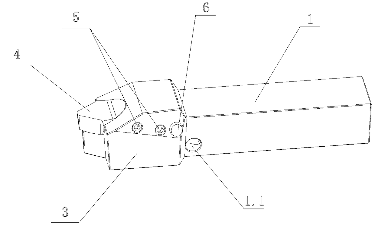
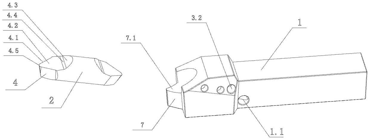
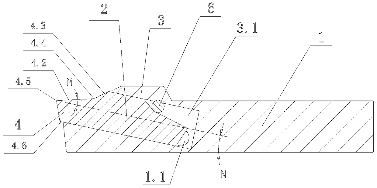
[0021] As shown in the figure, the present invention provides a machine-clip thread turning tool, which includes a tool handle 1 and a tool head body 2. The tool handle 1 is provided with a tool head connecting seat 3 for installing the tool head body 2. The tool The head body 2 is a cylindrical structure, and the end of the cutter head body 2 is cut along a plurality of cutting surfaces to form a cutter head 4. The cutter head connecting seat 3 is provided with a mounting hole 3.1 for inserting the cutter head body 2, and the cutter head The body 2 is slidably fitted in the installation hole 3.1, and the blade 4.1 of the cutter head 4 is exposed outside the cutter head connecting seat 3, and the cutter head connecting seat 3 is provided with a valve for limiting the movement of the cutter head body 2 relative to the cutter head connecting seat ...


PUM


Abstract

The invention discloses a mechanical clamp type threading tool. The mechanical clamp type threading tool comprises a tool handle (1) and a tool bit body (2). The tool handle (1) is provided with a tool bit connecting base (3) used for installing the tool bit body (2). The mechanical clamp type threading tool is characterized in that the tool bit body (2) is of a cylindrical structure, the end of the tool bit body (2) is cut into a tool bit (4) along a plurality of cutting faces, and the tool bit connecting base (3) is provided with an installing hole (3.1) allowing the tool bit body (2) to be inserted therein; the tool bit body (2) is in sliding fit with the installing hole (3.1), a cutting edge (4.1) of the tool bit (4) is exposed out of the tool bit connecting base (3), and the tool bit connecting base (3) is provided with a fastening mechanism used for limiting the tool bit body (2) to move relative to the tool bit connecting base (3). The mechanical clamp type threading tool is large in cutting feed amount and high in cutting speed.

Description

technical field [0001] The invention relates to the technical field of thread turning tools, in particular to a machine clamp type thread turning tool. Background technique [0002] The thread turning tool is a kind of cutting tool, which is a tool used for thread cutting on the turning machine tool. The clip-on thread turning tool is currently the most widely used thread turning tool in the industry. Its main structure includes two parts: the tool holder and the blade. Fastened by screws. Therefore, in the turning process of this existing machine-clamp type thread turning tool, the cutting reaction force that the blade is subjected to will be transmitted to the fastening screw, that is to say, the pressing force of the screw on the blade will affect the force of the blade. The upper limit value of the cutting reaction force that can be withstood. The number and size of screws that can be installed on the blade are just limited by the size of the blade itself. Therefore, ...

Claims


Application Information

Patent Timeline
Patent Type & Authority Patents(China)
IPC IPC(8): B23B27/00
CPCB23B27/00B23B27/16B23B2200/0409B23B2205/00
Inventor 袁国智任元平
Owner NINGBO CHUANJINGYU MECHANICAL TECH DEV
Learn More