a head planer

A technology of planer and bed, applied in milling machines, milling machine equipment, manufacturing tools, etc., can solve the problems of poor precision and low processing efficiency, and achieve the effect of improving processing efficiency, improving processing accuracy and increasing feed rate.

Active Publication Date: 2019-05-14
安庆安帝技益精机有限公司
View PDF10 Cites 0 Cited by
  • Summary
  • Abstract
  • Description
  • Claims
  • Application Information

AI Technical Summary

Problems solved by technology

[0003] The purpose of the present invention is to provide a planer, which solves the problems of low processing efficiency and poor precision of the traditional planer

Method used


Image

  • a head planer
  • a head planer

Examples


Embodiment Construction

[0020] In order to make the technical means, creative features, goals and effects of the present invention easy to understand, the present invention will be further described below in conjunction with specific illustrations.

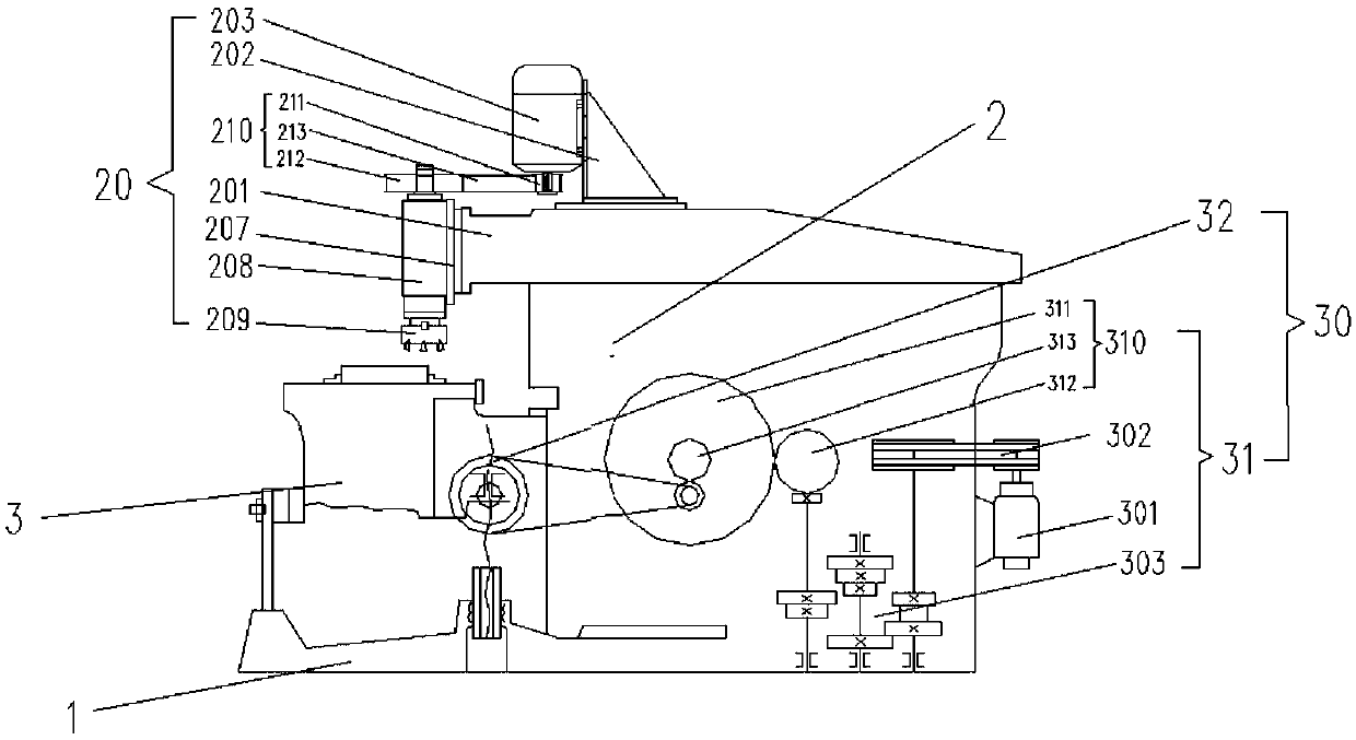
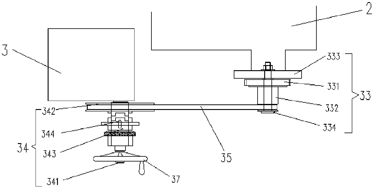
[0021] figure 1 Described, a kind of planer, comprises the bed 2 that is installed on the base 1 and the workbench 3, the main motion mechanism 20 that is arranged on the bed 2 top, and the workbench that is arranged on the bed 2 and the workbench 3 Give agency 30. A lifting device 36 for controlling the lifting movement of the workbench 3 is provided between the base 1 and the workbench 3 .

[0022] The main motion mechanism 20 includes a ram 201 fixedly installed on the bed, a first motor 203 arranged on the upper end of the ram 201 through a motor mounting plate 202, and a boring machine mounted on the front end of the ram 201 through a spindle grinding head mounting plate 207. Milling spindle grinding head 208, a synchronous transmission device 210...


PUM


Abstract

A novel shaping machine comprises a base, a machine body, a workbench, a main movement mechanism and a workbench feeding mechanism; the main movement mechanism comprises a ram fixedly mounted on the machine body, a first motor arranged at the upper end of the ram and a boring and milling spindle grinding head arranged at the front end of the ram; a synchronous transmission device is arranged between the first motor and the boring and milling spindle grinding head; a milling cutter disk is arranged at the bottom end of the boring and milling spindle grinding head; and the workbench feeding mechanism comprises a gear transmission mechanism arranged on the machine body and a belt pulley transmission mechanism, one end of the belt pulley transmission mechanism is arranged on the machine body, and the other end of the belt pulley transmission mechanism is arranged on the workbench. The main movement mechanism and the workbench feeding mechanism of the shaping machine are two completely independent mechanisms, main movement and feeding movement of the shaping machine are conducted simultaneously, and the machining efficiency is improved; and the main movement mechanism of the shaping machine is fixed on the machine body, so that the main movement of the shaping machine is relatively stable, and the machining precision is improved.

Description

technical field [0001] The invention relates to the technical field of machine tool processing and mechanical transmission, and more specifically relates to a planer. Background technique [0002] The main movement of the traditional bull planer is driven by the crank rocker mechanism, the moving speed of the ram is uneven and there is obvious impact phenomenon, because the ram of the traditional bull planer does not cut when it returns, and the workpiece feed motion is intermittent feed motion (planer A reciprocating motion workpiece is fed once) and is processed by a single-edged planer, which makes the workpiece processing efficiency lower and the accuracy poorer. Contents of the invention [0003] The object of the present invention is to provide a planer, which solves the problems of low processing efficiency and poor precision of the traditional planer. [0004] The technical problem to be solved by the present invention is realized by the following technical soluti...

Claims


Application Information

Patent Timeline
Patent Type & Authority Patents(China)
IPC IPC(8): B23C1/06B23Q5/10B23Q5/40B23Q5/34
CPCB23C1/06B23Q5/10B23Q5/34B23Q5/40
Inventor 张斌张青松程从科陈水林何宇豪
Owner 安庆安帝技益精机有限公司
Why Eureka
Try Eureka