Lighting device and backlight module applying same

A technology of light source device and backlight module, which is applied to the components of lighting devices, light sources, electric light sources, etc., which can solve the problems of insufficient light uniformity and uneven light intensity, and achieve the goal of reducing thickness and short light mixing distance Effect

Active Publication Date: 2011-03-23
CORETRONIC OPTICS (SUZHOU) CO LTD
View PDF1 Cites 9 Cited by
  • Summary
  • Abstract
  • Description
  • Claims
  • Application Information

AI Technical Summary

Problems solved by technology

However, the light beam emitted by the general LED light source is directional, and the light uniformity is not enough. Therefore, the light beam emitted by the LED light source needs to be equipped with a lens device to improve the uniformity of the emitted light beam. However, the actual application of the LED light source under various conditions There are still many challenges in improving the light uniformity
[0003] In order to improve the light uniformity of the light emitting diode light source, China Taiwan Patent No. TW521870 proposes an improved design, such as figure 1 As shown, the light source device 10 has light generated by light-emitting diodes inside, and some of the light rays are refracted by the convex lens on the top of the light source device 10 and become parallel outgoing lights, but part of the light rays that are emitted to the surroundings are due to refraction. Angle exit causes the intensity of the light exiting from the top to be uneven, which shows that there is still room for improvement in the design

Method used


Image

  • Lighting device and backlight module applying same
  • Lighting device and backlight module applying same
  • Lighting device and backlight module applying same

Examples


Embodiment Construction

[0052] The following descriptions of the various embodiments refer to the accompanying drawings to illustrate specific embodiments in which the present invention may be practiced. The directional terms mentioned in the present invention, such as "upper", "lower", "front", "rear", "left", "right", etc., are only referring to the directions of the attached drawings. Accordingly, the directional terms are used to illustrate, not to limit, the invention.

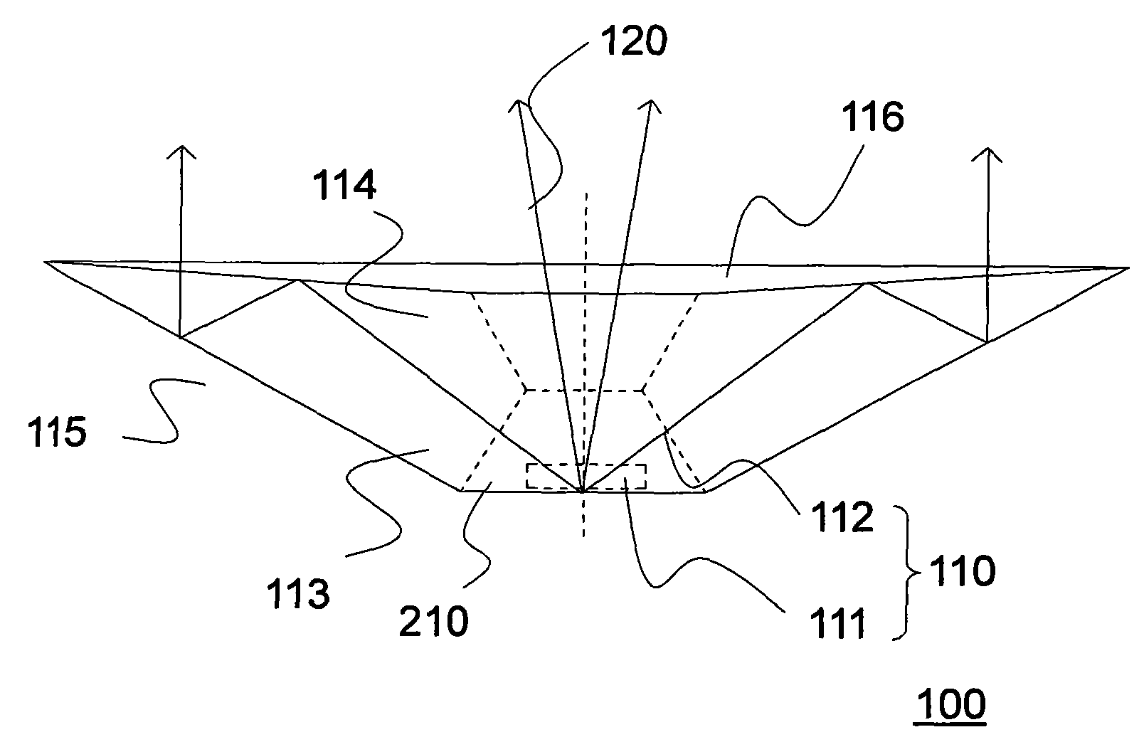
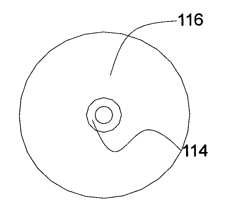
[0053] figure 2 It is a side view of a light source device according to an embodiment of the present invention. image 3 for figure 2 A top view of the light source device. Figure 4 for figure 2 A perspective view of the lens of the light source device. Please also refer to figure 2 , image 3 and Figure 4 , the light source device 100 according to an embodiment of the present invention includes a light source and a lens 110 . The light source has at least one LED 210 , which is suitable for emitting a light beam ...


PUM


Abstract

The invention relates to a lighting device and a backlight module applying the lighting device. The lighting device comprises a light source capable of emitting a light beam along an optical axis and a lens arranged on the transmission pathway of the light beam. The lens contains a hollow structure and a light guide part, one part of the light beam can penetrate the lens by virtue of the hollow structure along the optical axis, the light guide part is provided with a light emitting surface surrounding the hollow structure, the hollow structure penetrates the light guide part, and the other part of the light beam is transmitted to the light emitting surface to be emitted by virtue of the light guide part. The invention also provides a backlight module applying the lighting device. The invention can obtain good uniform light intensity distribution.

Description

【Technical field】 [0001] The present invention relates to a light source device and a backlight module using the same, and in particular to a light source device with uniform light intensity distribution and a backlight module using the same. 【Background technique】 [0002] In recent years, high-efficiency, power-saving, and long-life lighting light source devices have become a development trend. Light-emitting diode (LED) light sources are gradually replacing traditional light source devices, and are widely used in display lighting, indoor night lights, flashlights, outdoor traffic signs, vehicle lights, billboards and other fields. However, the light beam emitted by the general LED light source is directional, and the light uniformity is not enough. Therefore, the light beam emitted by the LED light source needs to be equipped with a lens device to improve the uniformity of the emitted light beam. However, the actual application of the LED light source under various condit...

Claims


Application Information

Patent Timeline
Patent Type & Authority Applications(China)
IPC IPC(8): F21S2/00F21V5/04F21V5/00F21Y101/02
Inventor 李秀富赵华
Owner CORETRONIC OPTICS (SUZHOU) CO LTD
Why Eureka
Try Eureka