Rotating electrical machine

A technology of rotating electrical machines and rotors, which is applied in the field of rotating electrical machines to achieve the effect of high duty ratio

Inactive Publication Date: 2011-03-23
HITACHI LTD
View PDF4 Cites 13 Cited by
  • Summary
  • Abstract
  • Description
  • Claims
  • Application Information

AI Technical Summary

Problems solved by technology

However, since the above-mentioned technology is an armature that rotates on the coil side, the teeth tip parts of the rotor core are arranged on the outer peripheral side.

Method used


Image

  • Rotating electrical machine
  • Rotating electrical machine
  • Rotating electrical machine

Examples


Embodiment Construction

[0024] The embodiments shown below are related to rotating electric machines such as electric motors and generators and their manufacturing methods, and relate to rotating electric machines equipped with a core stator (stator) with semi-closed slots formed by opening the teeth tip. .

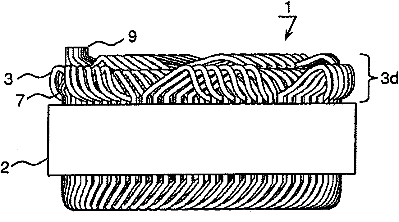
[0025] figure 1 This is a rotating electrical machine constituting one embodiment of the present invention. A stator 1 is shown in which coils are wound such that two stator poles formed by coil turns in the same phase are arranged within 360 degrees of the electrical angle formed by the magnetic poles of the rotor. Hereinafter, the coil formed by winding is referred to as a dispersed winding coil. Details of the dispersed winding coil will be described later.

[0026] figure 1 A front view of the stator 1 viewed from the side of the stator core 2 is shown, and the dispersed winding coil 7 is assembled to the stator core 2 and the end portion 9 of the wire 3 is connected. With this structur...


PUM


Abstract

The invention provides a rotating electrical machine. A tooth main body is connected with tooth tip edge portions by connecting portions with slits being formed in the coil sides of the connecting portions; and the slits extend from opening portions towards the centers of the tooth tip edge portions in circumferential direction, and are formed so that their tooth main body sides and their tip edge portion sides, that together define the opening portions of the slits, contact one another; with the gaps between adjacent ones of the tooth tip edge portions in circumferential direction being smaller than a width of the slot. The high duty ratio of the iron core in the iron core groove is high, the coil winding is simplified and the electronic characteristic is excellent.

Description

technical field [0001] The invention relates to a rotating electric machine. Background technique [0002] As the structure of the coil formed in the stator of the rotating electric machine, methods such as distributed winding and concentrated winding are known. Among them, from the viewpoint of reducing iron loss, it is desirable to integrally form the stator core of the distributed winding coils. In addition, from the viewpoint of reducing iron loss, it is desirable that the front ends of the teeth of the stator core have a structure in which the width of the front ends of the teeth of the stator core is wider than the width of the grooves of the stator core in which the coils are accommodated, that is, adjacent teeth The intervals between each other are narrow. [0003] For the winding method, it needs to be formed across the grooves of the stator core. Since the wire is wound from the inner diameter of the stator core to the groove, it is best to make the distance betw...

Claims


Application Information

Patent Timeline
Patent Type & Authority Applications(China)
IPC IPC(8): H02K1/22H02K1/14H02K1/16
CPCH02K1/165H02K3/487H02K15/0018
Inventor 长绳尚石川芳寿上野惠尉牧山高大本间雅彦梅崎洋介
Owner HITACHI LTD
Why Eureka
Try Eureka