Adaptive control of composite plycutting

An automatic controller and layer-laying technology, applied in thin material processing, metal processing, transportation and packaging, etc., can solve the problem of not using CNC ultrasonic cutting machine, etc., and achieve the effect of reducing the amount of programming

Active Publication Date: 2011-03-23
THE BOEING CO
View PDF0 Cites 6 Cited by
  • Summary
  • Abstract
  • Description
  • Claims
  • Application Information

AI Technical Summary

Problems solved by technology

However, such adaptive control techniques have not been applied to CNC ultrasonic cutting machines for cutting multiple plies of composite materials

Method used


Image

  • Adaptive control of composite plycutting
  • Adaptive control of composite plycutting
  • Adaptive control of composite plycutting

Examples


Embodiment Construction

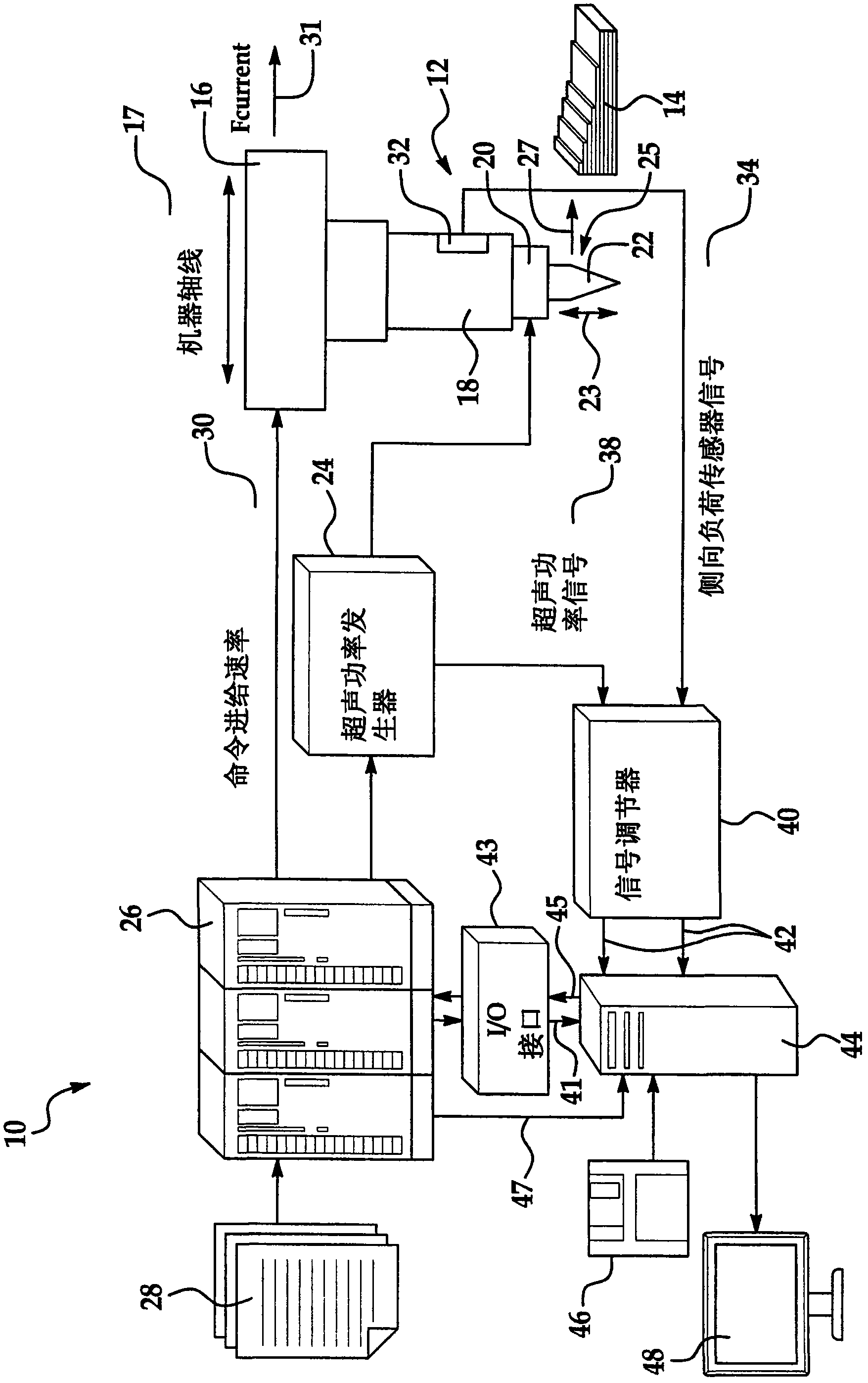
[0019] first reference figure 1 , which shows a system 10 for cutting a plurality of plies 14 of composite material using an automatically controlled ultrasonic cutter generally indicated by the numeral 12 . Although multiple plies 14 of composite material are shown in connection with the disclosed embodiments, it should be understood that individual plies of composite material as well as materials other than composite material may be cut. The layups may be raw (uncured) where the cutter 12 is used to cut the shape of the layups used to form the layups during the initial fabrication of the structure. However, embodiments of the present invention may also be used to cut partially or fully cured layups after a structure has been fabricated, such as during repair of composite aircraft components or subassemblies where a portion of the component / subassembly must be cut away.

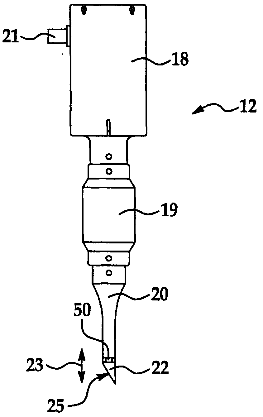
[0020] The ultrasonic cutter 12 is mounted on a toolhead 16 that is movable along a plurality of machine...


PUM


Abstract

The feed rate of an ultrasonic knife used to cut composite material is optimized using adaptive control. One or more parameters such as ultrasonic power or side load on the knife is sensed and used to generate feedback control signals. The feedback control signals are used to optimize the commanded feedrate of the knife.

Description

technical field [0001] The present invention relates generally to automatically controlled machine tools, and more particularly to systems and methods for automatically controlling the feed rate of an ultrasonic knife for cutting material, particularly multilayer composite materials. Background technique [0002] Ultrasonic cutters typically cut sheet and other materials with a knife powered by an ultrasonic transducer. One application of ultrasonic cutting machines is found in the field of composite materials, where multiple stacks or layers of uncured composite material forming a laminate are simultaneously cut into desired shapes using ultrasonically powered knives. In some cases, the ultrasonic cutting machine may be mounted on a CNC (Computer Numerically Controlled) controlled machine tool or machine tool that includes an automatic tape laying head capable of laying down and cutting multiple overlapping layers of composite tape. [0003] The process of cutting the comp...

Claims


Application Information

Patent Timeline
Patent Type & Authority Applications(China)
IPC IPC(8): B26D5/20B26D7/08
CPCB26D7/086B26D5/20B26F1/3813Y10T83/148Y10T428/31504
Inventor 徐良基S·K·霍勒丁R·A·克兰普
Owner THE BOEING CO
Why Eureka
Try Eureka