Solenoid valve with multiple-part armature without armature guide

A solenoid valve and armature technology, applied to engine components, machines/engines, fuel injection pumps, etc., can solve problems such as narrow tolerances, increased tolerance chains, laborious assembly, etc., and achieve the effect of small rebound tendency

Inactive Publication Date: 2011-03-23
ROBERT BOSCH GMBH
View PDF9 Cites 14 Cited by
  • Summary
  • Abstract
  • Description
  • Claims
  • Application Information

AI Technical Summary

Problems solved by technology

The disadvantage is that the number of components to be assembled increases and therefore the tolerance chain increases
In order to adjust a given stroke, the tolerances of the elements to be connected (cooperating pin, armature pin and armature plate and receiving hole for cooperating pin) have to be kept very narrow, and moreover result in a very laborious assembly

Method used


Image

  • Solenoid valve with multiple-part armature without armature guide
  • Solenoid valve with multiple-part armature without armature guide
  • Solenoid valve with multiple-part armature without armature guide

Examples


Embodiment Construction

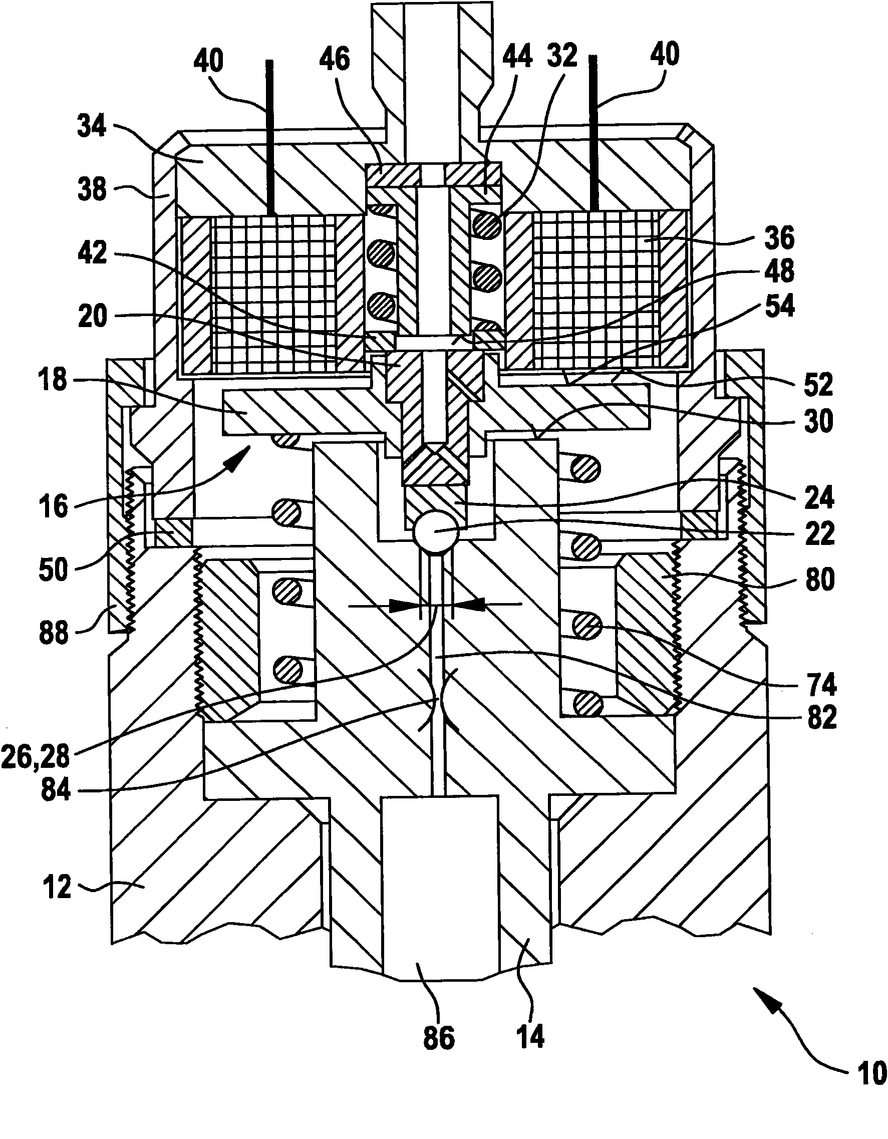
[0014] figure 1 The solenoid valve proposed according to the invention for operating a fuel injector is shown in a rest phase, ie when the solenoid coil is not energized.

[0015] Such as figure 1 As shown, the fuel injector 10 includes a solenoid valve which essentially includes a multi-part armature 16 with an armature plate 18 and an armature pin 20 and a solenoid coil 36 received in a solenoid sleeve 38 . The solenoid coil 36 of the solenoid valve is energized via the depicted electrical contact 40 .

[0016] The fuel injector 10 includes an injector body 12 in which a valve block 14 is received. Inside the valve block 14 there is a control chamber 86 which is passed through the figure 1 The meter-in structure, not shown, is loaded with fuel at system pressure. The pressure level inside the control chamber 86 of the valve block 14 corresponds to the system pressure p or the control pressure p generated by the high-pressure delivery unit (such as a high-pressure deliver...


PUM


Abstract

The invention relates to a solenoid valve (16, 36) for actuating a fuel injector (10). The latter comprises a valve piece (14), in which a control chamber (86) is formed. Its outlet (82) can be opened or closed by way of a closing element (22) which can be actuated via the solenoid valve (16, 36). An armature plate (18) is received in a hydraulically damped manner (72, 56, 73) on an armature pin (20) which has a central outlet (62).

Description

Background technique [0001] DE 196 50 865 A1 describes a solenoid valve for controlling the fuel pressure in a control chamber of an injection valve of, for example, a common rail injection system. The stroke movement of the valve piston is controlled by the fuel pressure in the control chamber, and the injection orifice of the injection valve is opened or closed by the valve piston. The solenoid valve comprises an electromagnet, a moving armature and a valve element which moves with the armature and is loaded in the closing direction by the valve closing spring, which cooperates with the valve seat of the solenoid valve and thereby controls the flow from the control chamber. fuel drain. [0002] In the known solenoid valves, vibrations of the armature and / or bounce of the valve part that occur during operation have a disadvantageous effect. According to the solutions of DE 196 50 865 A1 and DE 195 08 104 A1, the armature of the solenoid valve is constructed as a two-part so...

Claims


Application Information

Patent Timeline
Patent Type & Authority Applications(China)
IPC IPC(8): F02M47/02F02M59/46F02M61/20F02M63/00
CPCF02M61/20F02M63/0043F02M63/0042F02M63/0078F02M63/0015F02M63/004F02M2200/304F02M63/0024F02M47/027
Inventor M・库尔茨
Owner ROBERT BOSCH GMBH
Why Eureka
Try Eureka