
Spindle transporting trolley

A technology for transporting ingots and trolleys, which is applied in the field of ingot transporting trolleys, which can solve problems such as hindering the manipulator track, low work efficiency, and affecting forging quality, and achieve the effect of simple control, improved work efficiency, and easy control automation

Active Publication Date: 2011-03-30
MCC CAPITAL ENGINEERING & RESEARCH
View PDF8 Cites 10 Cited by
  • Summary
  • Abstract
  • Description
  • Claims
  • Application Information

AI Technical Summary

Problems solved by technology

[0002] In the current field of forging and forging technology, various presses are developing towards high precision, numerical control, automation, networking, and high production efficiency. The high production efficiency of rapid free forging is not only reflected in the high speed of the press itself, High efficiency, high automation and high efficiency of auxiliary processes and auxiliary equipment in forging production also play a very important role. For example, before the press press forges steel ingots and other raw materials, the steel ingots must be transported to the appropriate position by the conveying equipment. In order to facilitate the mechanical structure of the press to operate the steel ingot, and in order to realize the smooth operation of the press, the angle and height of the position of the steel ingot should be precisely controlled, and subsequently, in order to meet the above requirements, the conveying equipment, It will take a long time to adjust, and the work efficiency is low. Even under some special working conditions, even if it takes a long time to adjust, it still cannot meet the relevant precision requirements, which will affect the quality of forging.
[0003] For example, the common conveying equipment in the prior art is the lifting and rotating table, which is installed in the track of the manipulator, which has the function of lifting and rotating. machine track, and rotate to adjust the angle for the press to carry out the forging operation, but the work efficiency of the lifting rotary table is low, and the accuracy of the rotation positioning is also low. In some cases where the working space is insufficient, this lifting rotary table Inconvenient to set up, there may be problems blocking the manipulator track

Method used


Image

  • Spindle transporting trolley
  • Spindle transporting trolley
  • Spindle transporting trolley

Examples


Embodiment Construction

[0066] In order to have a clearer understanding of the technical features, purposes and effects of the present invention, the specific implementation of the present invention will now be described with reference to the accompanying drawings, but those skilled in the art should understand that this is not a limitation.

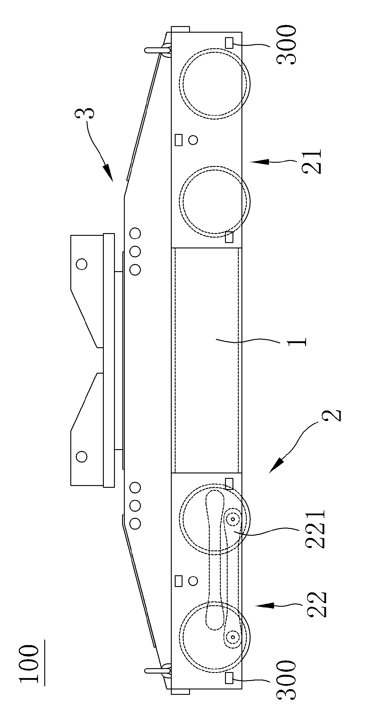
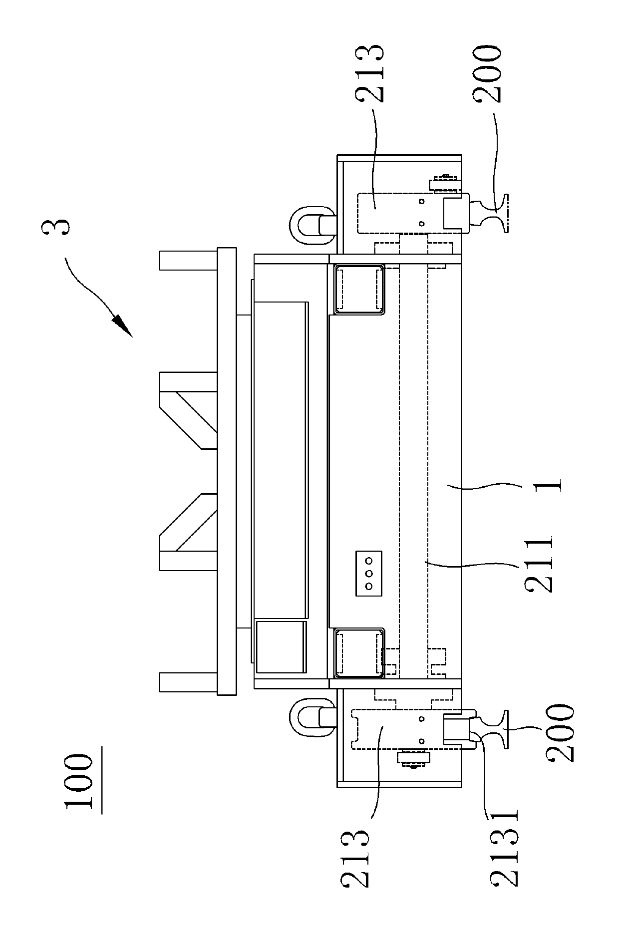
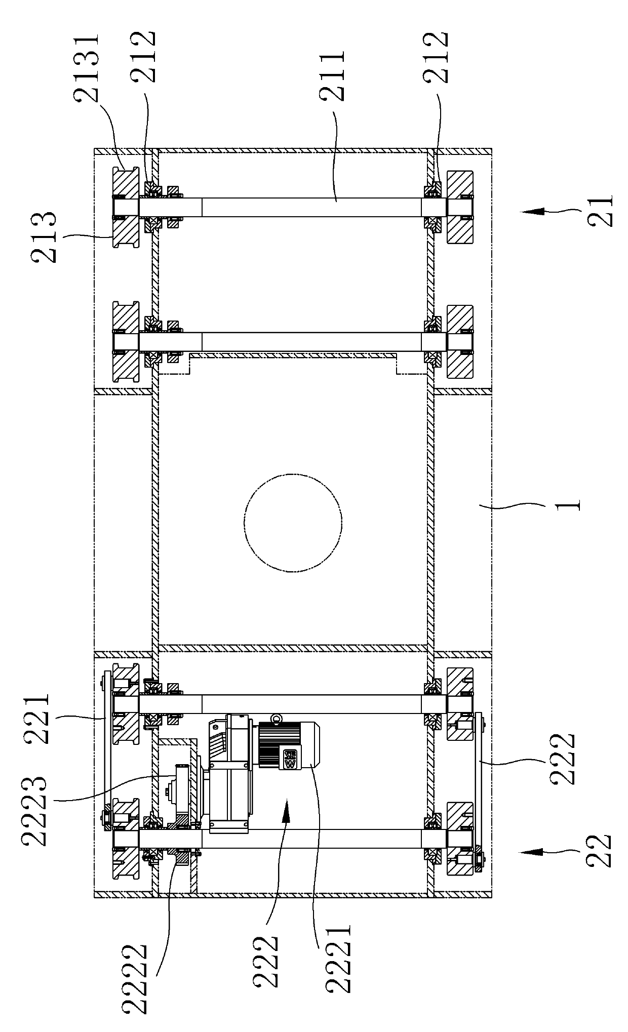
[0067] Please refer to figure 1 and figure 2 ,in figure 1 It is a schematic diagram of the overall front view of the ingot transport trolley of the present invention, figure 2 It is a schematic diagram of the overall side view of the ingot transporting trolley of the present invention. As shown in the figure, the ingot transporting trolley 100 of the present invention mainly includes: a car body 1, a traveling mechanism 2 and a rotating mechanism 3, wherein the traveling mechanism 2 is arranged at the bottom of the car body 1, and its It is mainly used to drive the ingot conveying trolley 100 to make it move; the rotating mechanism 3 is arranged on the car ...


PUM


Abstract

The invention discloses a spindle transporting trolley arranged on a spindle transporting trolley track which is intersected with the traditional operator track. The spindle transporting trolley comprises a trolley body, a running device and a rotating mechanism, wherein the running mechanism is arranged at the bottom of the trolley body and used for driving the spindle transporting trolley to run on the spindle transporting trolley track; and the rotating mechanism is arranged on the trolley body and used for loading and rotationally positioning forged members. The spindle transporting trolley can greatly shorten the forging, pressing and feeding time to effectively improve the working efficiency of the whole forging and pressing machine equipment, is accurate to position, and can improve the forging and pressing quality.

Description

technical field [0001] The invention relates to forging conveying equipment, in particular to an ingot conveying trolley. Background technique [0002] In the current field of forging and forging technology, various presses are developing towards high precision, numerical control, automation, networking, and high production efficiency. The high production efficiency of rapid free forging is not only reflected in the high speed of the press itself, High efficiency, high automation and high efficiency of auxiliary processes and auxiliary equipment in forging production also play a very important role. For example, before the press press forges steel ingots and other raw materials, the steel ingots must be transported to the appropriate position by the conveying equipment. In order to facilitate the mechanical structure of the press to operate the steel ingot, and in order to realize the smooth operation of the press, the angle and height of the position of the steel ingot shou...

Claims


Application Information

Patent Timeline
IPC IPC(8): B22D29/04
Inventor 黄木林怀峰王震王燕红
Owner MCC CAPITAL ENGINEERING & RESEARCH
Learn More