
Method of friction welding

A friction welding and welding surface technology, which is applied in welding equipment, welding/welding/cutting items, non-electric welding equipment, etc., can solve the problems of reducing benefits and damage

Inactive Publication Date: 2015-02-18
ROLLS ROYCE PLC
View PDF7 Cites 0 Cited by
  • Summary
  • Abstract
  • Description
  • Claims
  • Application Information

AI Technical Summary

Problems solved by technology

[0003] However, it has been found that for large cone angles the edge of the first welding surface fails due to lack of support and this results in reduced control of the contact area and the aforementioned pressure etc.
Therefore, the method of WO2008017800A1 can only be used for low cone angles and this reduces the benefit of the method of WO2008017800A1

Method used


Image

  • Method of friction welding
  • Method of friction welding
  • Method of friction welding

Examples


Embodiment Construction

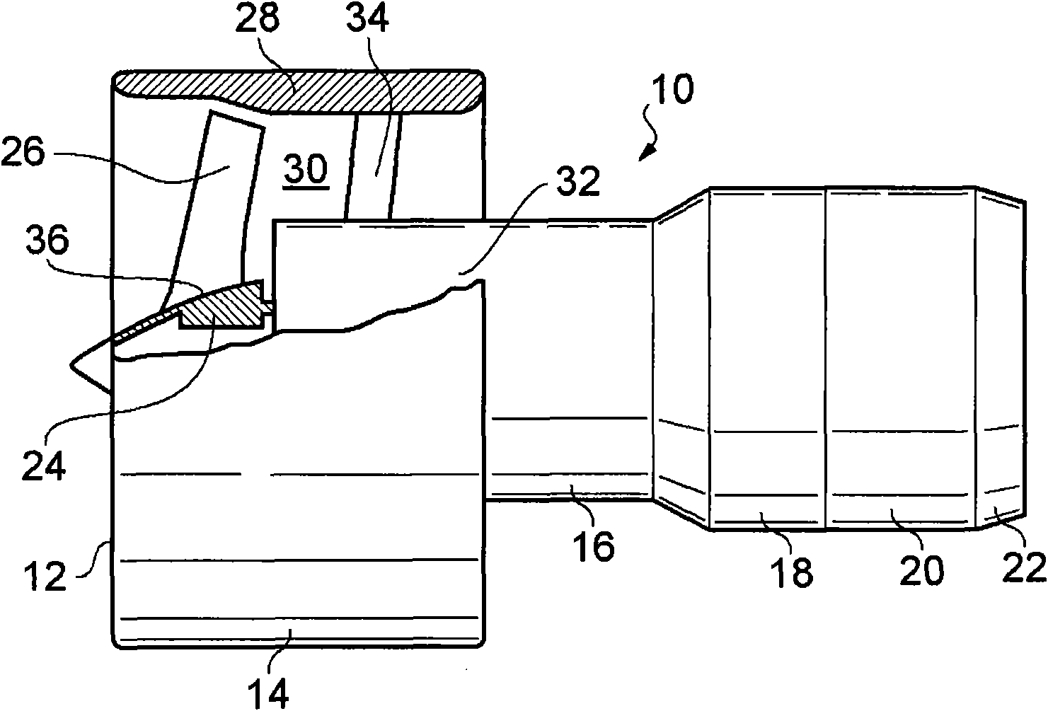
[0032] Such as figure 1 As shown, fan turbine gas turbine engine 10 includes, in flow order: inlet 12 , fan section 14 , compressor section 16 , combustion section 18 , turbine section 20 , and exhaust 22 . The fan section 14 includes a fan rotor 24 carrying a plurality of circumferentially spaced radially outwardly extending fan blades 26 . Fan section 14 also includes a fan case 28 arranged coaxially with and surrounding fan rotor 24 and fan blades 26 . The fan case 28 defines a fan duct 30 . The fan case 28 is secured to the core engine case 32 by a plurality of circumferentially spaced apart and radially extending fan outlet vanes 34 .

[0033] Compressor section 16 includes one or more compressors, such as an intermediate pressure compressor (not shown) and a high pressure compressor (not shown) or a high pressure compressor (not shown). Turbine section 20 includes one or more turbines, such as a high pressure turbine (not shown), an intermediate pressure turbine (not ...


PUM


Abstract

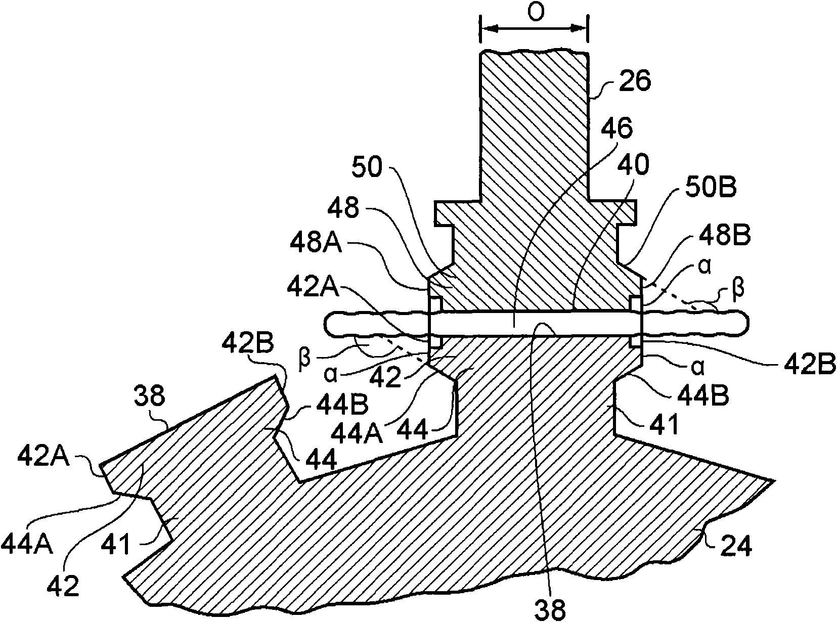
A method of friction welding comprising providing a first workpiece (24) having a first weld surface (38) and a second workpiece (26) having a second weld surface (40). In a first region (42) adjacent the first weld surface (38) the first workpiece (24) is arranged at an angle (±) of substantially 90° to the first weld surface (38) and in a second region (44) adjacent to the first region (42) the first workpiece (24) tapers away from the first weld surface (38). The first workpiece (24) is arranged such that in the second region (44) the first workpiece (24) is arranged at an angle (²) greater than 90° and less than 180° to the first weld surface (38). The first and second workpieces (24, 26) are arranged such that first weld surface (38) of the first workpiece (24) abuts the second weld surface (40) of the second workpiece (26). The first and second workpieces (24, 26) are moved relative to each other such that the temperature increases at the weld surfaces (38, 40) to create a weld interface (46) and then the movement is stopped to cool to weld the first and second workpieces (24, 26) together.

Description

technical field [0001] The present invention relates to a method of friction welding, in particular, to a method of linear friction welding, a method of rotating friction welding or a method of orbital friction welding. Background technique [0002] WO2008017800A1 describes a method of friction welding in which a first workpiece is arranged with a gradually decreasing inclination away from the first welding surface and converges in a direction away from the first welding surface. This can reduce the flow rate of flash weld material during friction welding to reduce stress induced porosity generation at the weld edges. [0003] However, it has been found that for large cone angles the edge of the first welding surface breaks down due to lack of support and this leads to reduced control of the contact area and the aforementioned pressure etc. Therefore, the method of WO2008017800A1 can only be used for low cone angles and this reduces the benefit of the method of WO2008017800...

Claims


Application Information

Patent Timeline
Patent Type & Authority Patents(China)
IPC IPC(8): B23K20/12B23K33/00B23K101/00
CPCB23K20/12B23K20/1205B23K20/129F01D5/34B23K2201/001B23K33/004F01D5/3061F05B2230/239B23K2101/001
Inventor S·E·布雷M·D·劳尔森
Owner ROLLS ROYCE PLC
Learn More