
Cutting device for cutting a thin and adhesive belt, in particular a cord belt

A technology of cutting equipment and cord belts, applied in the field of cutting equipment, can solve the problems of complicated design of a pressing device, etc., and achieve the effect of simple structure

Active Publication Date: 2011-03-30
KARL EUGEN FISCHER
View PDF6 Cites 19 Cited by
  • Summary
  • Abstract
  • Description
  • Claims
  • Application Information

AI Technical Summary

Problems solved by technology

[0007] In addition, the design of the holding-down device is complex, since a hollow carrier must be provide

Method used


Image

  • Cutting device for cutting a thin and adhesive belt, in particular a cord belt
  • Cutting device for cutting a thin and adhesive belt, in particular a cord belt
  • Cutting device for cutting a thin and adhesive belt, in particular a cord belt

Examples


Example Embodiment

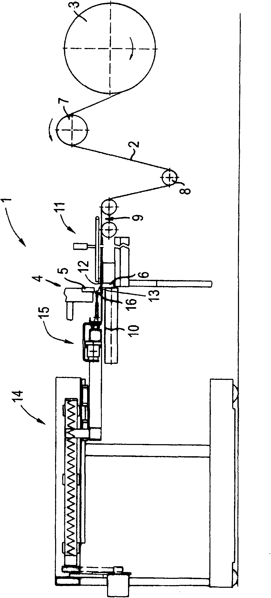
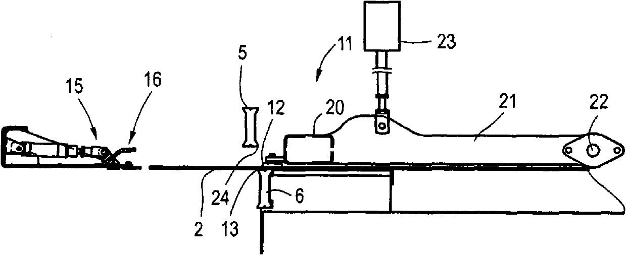
[0025] figure 1 A cutting device 1 according to the invention is shown with which a cord strip 2 drawn from a supply roll 3 can be cut. The cutting device 1 comprises a cutting device 4 comprising a vertically movable upper knife 5 and a stationary lower knife 6 . The cord strip 2 is guided via guide wheels / rollers 7 , 8 to the cutting device 1 where it is fed to an incoming conveyor belt 9 . Depending on the cutting angle with respect to the longitudinal direction of the cord strip 2 , the incoming conveyor belt 9 can be swung around a vertical axis from the vertical orientation of its longitudinal axis to the cutting edges of the lower knife 6 and the upper knife 5 accordingly. The cut cord lengths are transported via a delivery conveyor 10 to a downstream processing unit, for example a joining device.

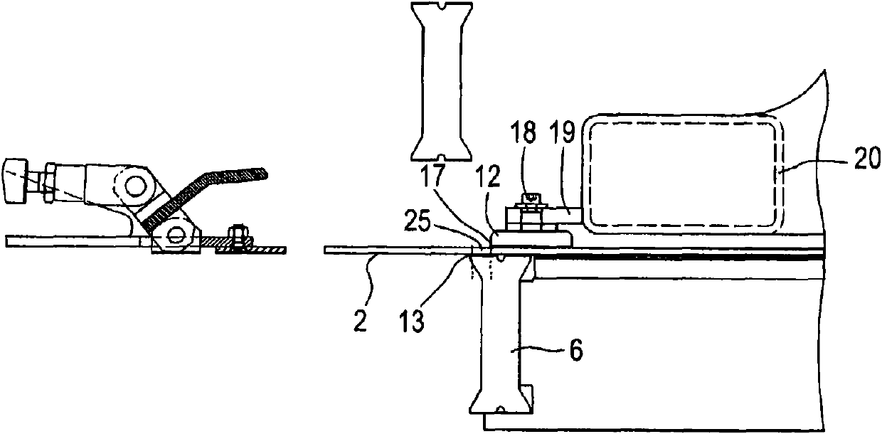
[0026] In order to fix the position of the cord strip 2 to be cut in the area of ​​the cutting edge, a hold-down device 11 is provided, which comprises a magnetic slat 12,...


PUM


Abstract

The present invention relates to a cutting device for cutting a thin and adhesive belt, in particular a cord belt. The device includes an upper cutter and a lower cutter, a pulling member for pulling a belt to be cut to pass through the cutters, and a pressing member falling to the belt from the upper side, the pressing member includes a magnetic batten for fixing the belt, the magnetic batten cooperates with a metal element contained in the belt or a fastening plate arranged under the belt directly, such that the front edge of the belt can be lifted to be held by a holding section of the pulling member, wherein the magnetic batten (12) directly pushes the belt (2) on the lower cutter (6) or an intermediate plate (36) joined to the lower cutter (6) in a position in which the belt (2) is suppressed.

Description

technical field [0001] The invention relates to a cutting device for cutting thin adhesive strips, especially cordbands, comprising an upper knife and a lower knife for pulling the strip area to be cut A pulling device through which a section passes through the knife and a pressing device which can be dropped onto the belt from the upper side, the pressing device comprising magnetic slats for fixing the belt, the magnetic slats directly Cooperate with the metal element contained in the belt or the clamping plate arranged below the belt in such a way that the leading edge of the belt can be raised in order to be grasped by the clamping section of the pulling device live. Background technique [0002] Such a cutting device is known, for example, from EP 1 243 404 B1. Such a cutting device is used to cut a section of precisely defined length from a continuous / endless strip drawn off from an unwinding wheel. Such belts are, for example, textile or steel cord belts, which are ...

Claims


Application Information

Patent Timeline
IPC IPC(8): B29D30/46B65H20/18B65H35/06
CPCB26D7/025B26D1/08B26D7/0633B26D3/003B29D30/46B29D2030/463
Inventor B・霍夫曼
Owner KARL EUGEN FISCHER
Learn More