Dehydrator

A dewatering machine, shell technology, applied in textile processing machine accessories, textiles and papermaking, liquid/gas/vapor removal by centrifugal force, etc., to achieve the effect of low loss rate, long brake service life, and reduced wear

Inactive Publication Date: 2011-03-30
华美线业有限公司
View PDF1 Cites 9 Cited by
  • Summary
  • Abstract
  • Description
  • Claims
  • Application Information

AI Technical Summary

Problems solved by technology

But its disadvantage is the same as above,

Method used


Image

  • Dehydrator
  • Dehydrator
  • Dehydrator

Examples


Embodiment Construction

[0019] The present invention will be further described in detail below in conjunction with the accompanying drawings and embodiments.

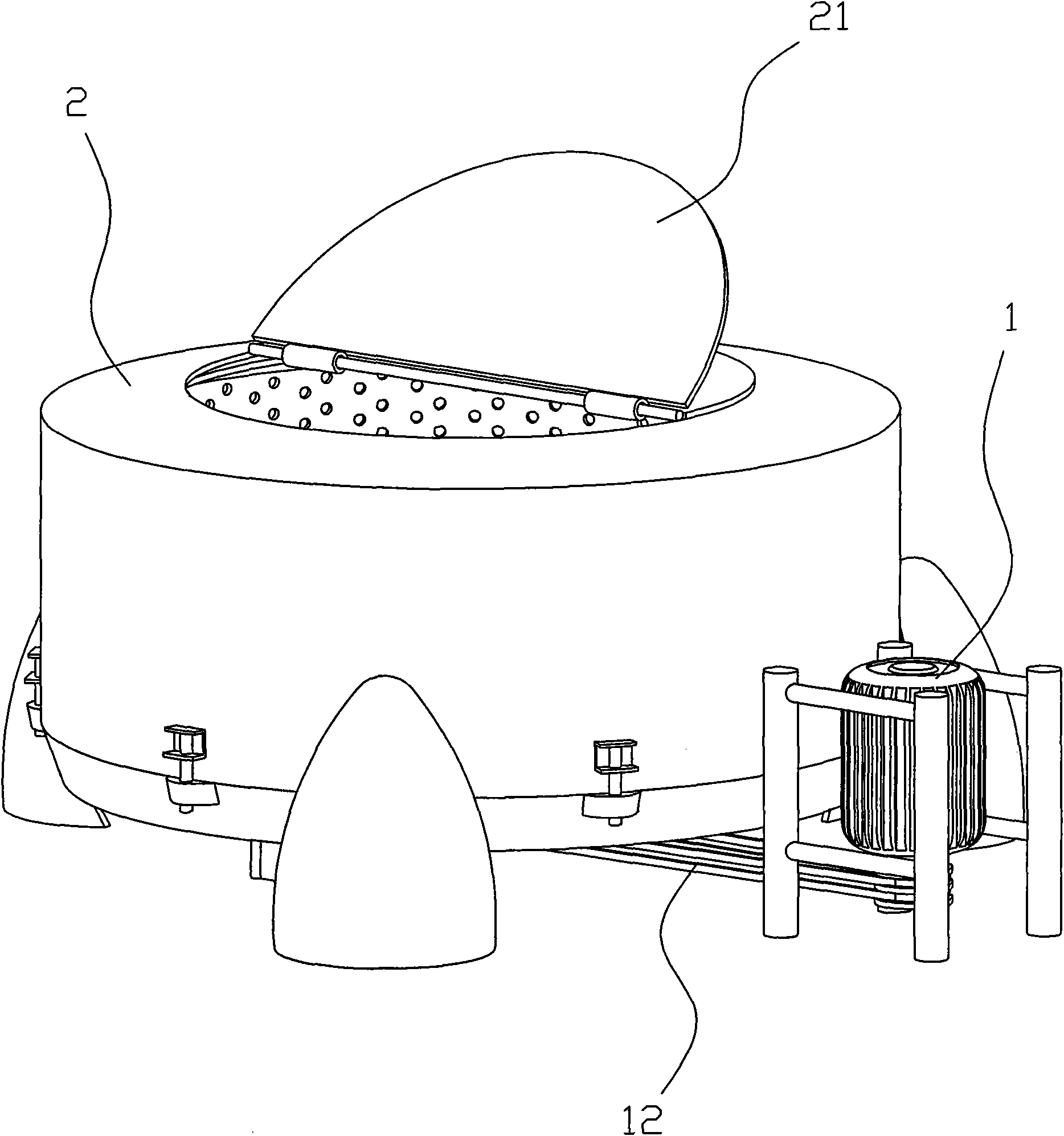
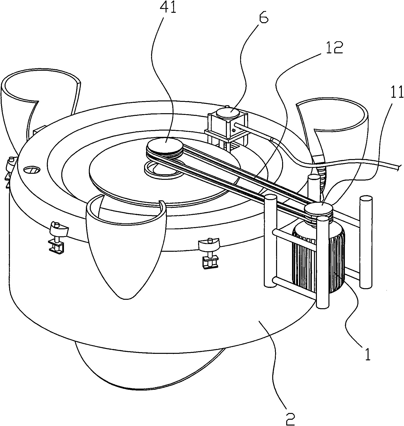
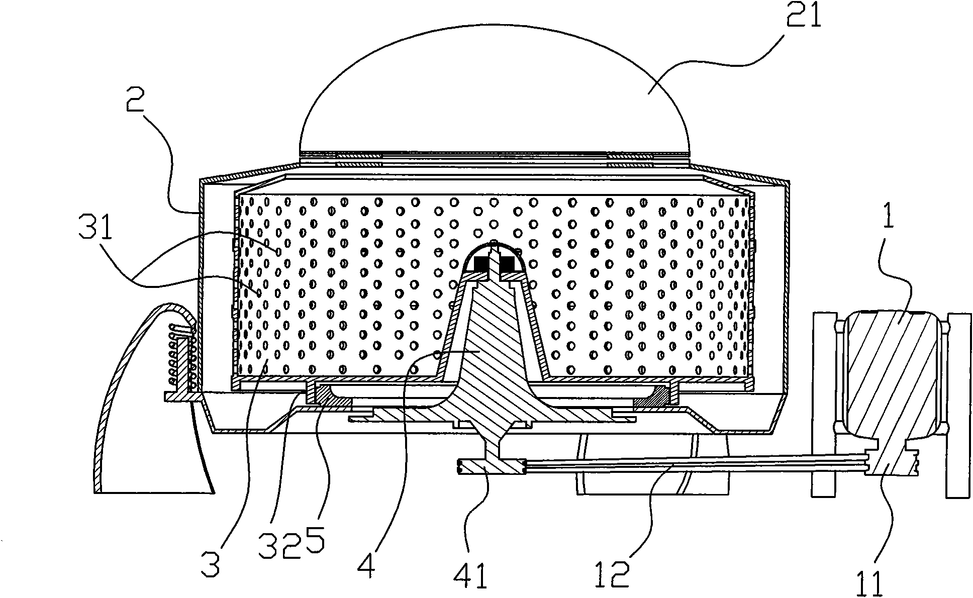
[0020] Such as Figure 1 to Figure 8 As shown, the dehydrator in this embodiment includes a casing 2 and a drum 3 with through holes 31 distributed on the sides, and an openable and closable cover plate 21 is provided at the top opening of the casing 2 . The rotating drum 3 is rotatably arranged in the casing 2, and the rotating drum 3 is connected with the output shaft of the motor 1 arranged outside the casing 2 through a transmission device, and the tops of the rotating drum 3 and the casing 2 are respectively provided with openings. An annular brake ring 32 extends downwards from the lower surface of the bottom of the drum 3, and an expandable and contractible annular brake rail 5 is arranged on the bottom of the casing 2. The outer surface of the annular brake rail 5 is tightened The ring-shaped brake pad 51 is pasted and fixed. After th...


PUM


Abstract

The invention relates to a dehydrator. The dehydrator comprises a shell (2) and a rotating drum (3), wherein through holes (31) are distributed on the side face of the rotating drum (3); the lower surface of the bottom of the rotating drum (3) stretches downward to form a circular brake ring (32); a circular brake rail (5) which can be extended and retracted are arranged at the bottom of the shell (2); an annular brake pad (51) is tightly adhered and fixed on the outer side face of the circular brake rail (5); an oval rotating body (7) is movably embedded between the two ends of the circular brake rail (5); a spring (52) making the circular brake rail (5) retracted is connected to the two ends of the circular brake rail (5); and a vertical rotating shaft (71) of the oval rotating body (7)is connected with an electrical appliance controller. The dehydrator with the structure has the advantages that: data are input into the electrical appliance controller, the dehydrator can be automatically braked after a motor of the dehydrator stops working, and the rotating drum of the dehydrator is stopped; and the wastage rate of the annular brake pad is low, the service life of a brake is long, and the braking time is shorter due to the regulation reasonableness of the electrical appliance controller, so that dehydrating efficiency is higher.

Description

technical field [0001] The present invention relates to a dehydrator for dyed yarn. Background technique [0002] The dehydration process in the bleaching and dyeing workshop of the thread factory is a very important part of production. The speed of dehydration and the dehydration rate can directly affect the production process, product quality and finished product rate. The existing dehydrator uses a manual brake device, that is, after the motor stops running within a specified time, the dehydrator still rotates at a high speed due to the effect of inertia. Because the manual brake cannot accurately grasp the timing of the brake, it often causes premature braking. The friction between the brake pad and the centrifuge increases, not only the dehydration rate is low, but also the brake loss rate is large, resulting in a short brake life and troubles for production and maintenance. [0003] An existing Chinese utility model patent No. CN200720036587.7 titled "A Dehydrator" di...

Claims


Application Information

Patent Timeline
IPC IPC(8): D06B15/10D06B23/00
Inventor 毛羽康史建民忻静祥
Owner 华美线业有限公司
Why Eureka
Try Eureka