
Suction disc

A technology of suction cups and suction parts, which is applied to suction cups, connecting components, mechanical equipment, etc., can solve the problems of increased manufacturing costs, easily damaged suction cup parts, and many processes, and achieves long service life, low processing cost, and smooth curtain surface. smooth effect

Inactive Publication Date: 2011-03-30
费小冰
View PDF7 Cites 2 Cited by
  • Summary
  • Abstract
  • Description
  • Claims
  • Application Information

AI Technical Summary

Problems solved by technology

When in use, because the two circular inserts of the suction cup are integrally designed with the suction part, they cannot be separated. Between the shaped block and the suction part, the actual operation is laborious, and it is easy to damage the suction cup parts, especially in winter when the temperature is low. Rust will affect the appearance of the product. Moreover, there will be burrs on the surface of the metal ring, which will easily pierce the sunshade itself and reduce the service life of the sunshade
[0003] On the other hand, the existing suction cups have no supporting effect on the curtain surface of the sunshade curtain. In actual use, the sunshade curtain is not easy to fit the automobile glass, and the curtain surface is uneven. Then relative to the car glass, it will be tilted outward, which will affect the sunshade effect.
[0004] At present, most of the suction cups on the sunshade on the market are easy to separate from the sunshade itself. In the actual use process, children are easy to take it off and enter it by mistake, and there are certain safety hazards.

Method used


Image

  • Suction disc
  • Suction disc
  • Suction disc

Examples


Embodiment 1

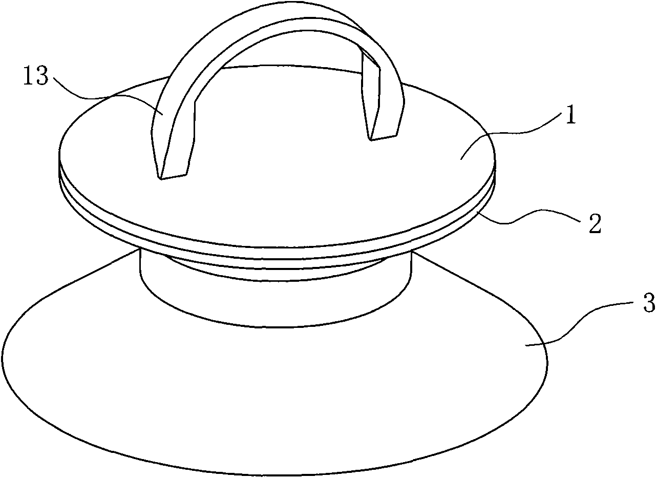
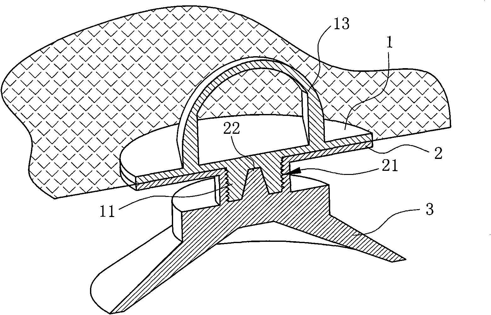
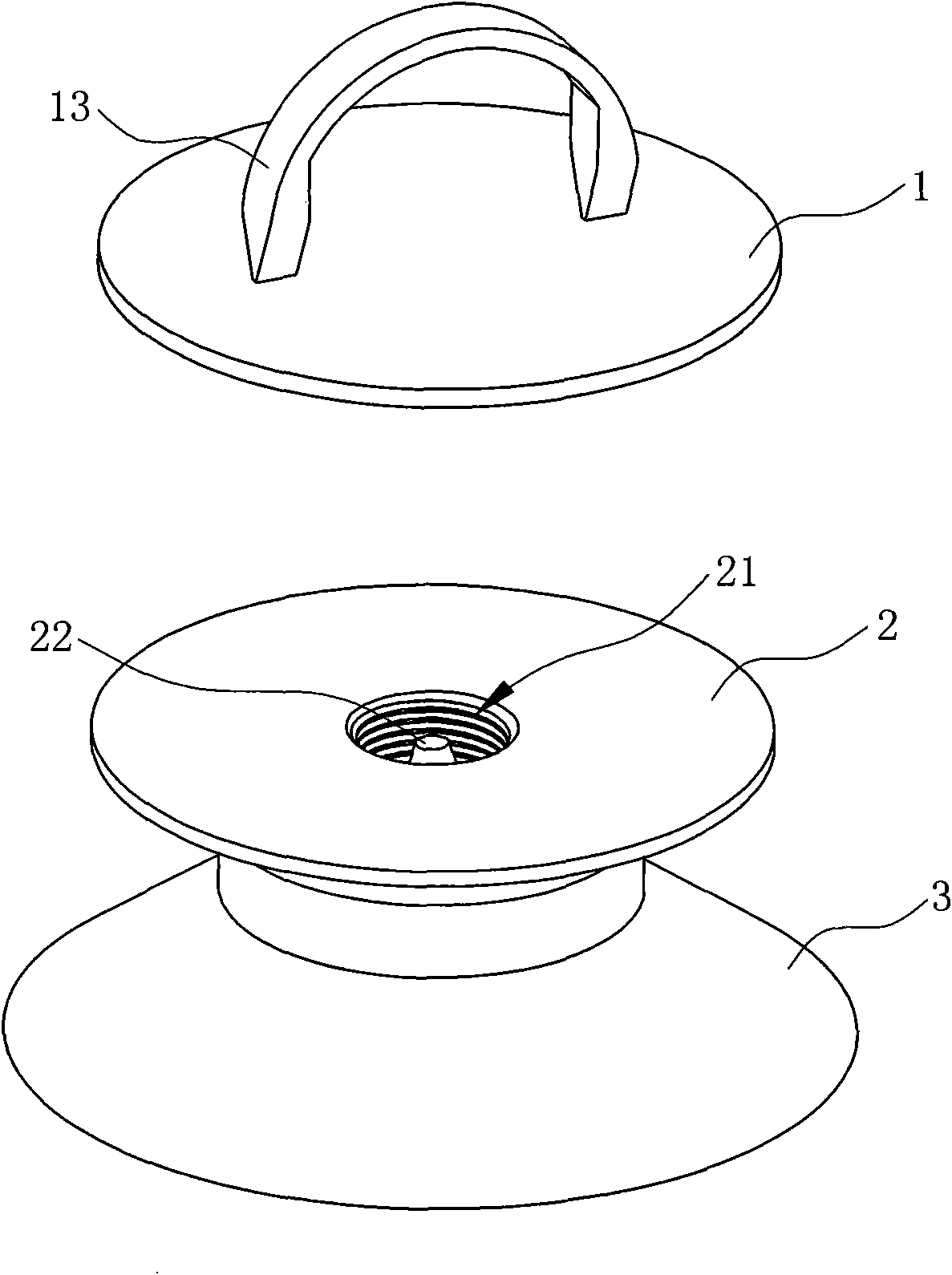
[0026] Such as Figure 1 ~ Figure 4 As shown, the suction cup includes a suction part 3 and a first support surface 1 and a second support surface 2 arranged on the suction part 3 in sequence from top to bottom;

[0027] Wherein, the suction part 3 is similar to the suction part on a common sucker, and can be adsorbed on a smooth surface. The suction part 3 and the second support surface 2 are integrally manufactured, and the surface of the first support surface 1 is provided with a pull ring 13 ;

[0028] The first supporting surface 1 and the second supporting surface 2 are detachably connected together through threaded connection, specifically: an outwardly protruding threaded connecting column 11 is provided at the center of the bottom of the first supporting surface 1, and the The surface of the second support surface 2 is correspondingly provided with a screw hole 21, and the threaded connection column 11 can be screwed into the screw hole 21 to realize the movable sepa...

Embodiment 2

[0032] Such as Figure 5 As shown, the difference between this embodiment and Embodiment 1 is that: the surface of the first support surface 1 is provided with a "one"-shaped fastening groove 14. 1 screwed onto the second support surface 2.


PUM


Abstract

The invention relates to a suction disc, which is positioned at the position of a small hole of a mounting piece. The suction disc comprises a suction part (3), wherein a first supporting surface (1) and a second supporting surface (2), which are greater than the small hole, are arranged on the suction part (3) in turn from top down; a connecting piece which corresponds to the small hole and can make the first supporting surface (1) and the second supporting surface (2) joint tightly is arranged between the first supporting surface (1) and the second supporting surface (2); and the first supporting surface (1) and the second supporting surface (2) can be movably and detachably connected together through the connecting piece. Compared with the prior art, the suction disc has the advantages that: it is convention and reliable to mount the suction disc on an automobile sunshade curtain with the two movable and detachable supporting surfaces arranged above the suction part; it is only a small hole that is needed to form on the automobile sunshade curtain, which lowers the overall processing cost and makes it more suitable for the suction disc to be used on the automobile sunshade curtain; and supported by the two supporting surfaces, the curtain surface of the automobile sunshade curtain is smoother and is well attached onto the side surface of automobile glass.

Description

technical field [0001] The invention relates to a suction cup, in particular to a suction cup which can be used for automobile sunshades. Background technique [0002] Car sunshades are mostly positioned on the windshield or window of the car by suction cups. Just disclose a kind of sucker structure in " a kind of structurally improved car sunshade sucker " that Chinese patent announcement number is CN2495495Y, and this sucker is provided with two circular inserts that are arranged at intervals on the rear side of the sucking part. The circumferences of the two circular embedding pieces are all larger than the metal sheet holes fixed in the center of the sunshade curtain, and a pull-off strip is also connected on the side of the outer edge of the suction cup. When in use, because the two circular inserts of the suction cup are integrally designed with the suction part, they cannot be separated. Between the shaped block and the suction part, the actual operation is laboriou...

Claims


Application Information

Patent Timeline
IPC IPC(8): F16B47/00
Inventor 费小冰
Owner 费小冰
Features
  • Generate Ideas
  • Intellectual Property
  • Life Sciences
  • Materials
  • Tech Scout
  • Unparalleled Data Quality
  • Higher Quality Content
  • 60% Fewer Hallucinations
Learn More