
Photoelectric integrated testing system and photoelectric testing method

A test system and integrated technology, applied in optics, nonlinear optics, instruments, etc., can solve the problems of longitudinal comparison of test results and centralized analysis of adverse effects, different test sample states and test environments, and large footprint. Achieve the effect of intensification, high efficiency, and reduction of floor space

Active Publication Date: 2012-07-18
BOE TECH GRP CO LTD +1
View PDF4 Cites 0 Cited by
  • Summary
  • Abstract
  • Description
  • Claims
  • Application Information

AI Technical Summary

Problems solved by technology

Due to the different test items, the test equipment used is also different, and the test of a sample of a liquid crystal display panel usually needs to be constantly moved between different test equipment, resulting in the state of the test sample and the test environment in each test. All are different, which will have an adverse effect on the longitudinal comparison and centralized analysis of the test results of the same test sample
In addition, since the test equipment corresponding to each test is different, and each test equipment has a separate supporting component, it occupies a large area, especially for the test of large-sized products, the use area of ​​the equipment will be larger, making overall cost increase

Method used


Image

  • Photoelectric integrated testing system and photoelectric testing method
  • Photoelectric integrated testing system and photoelectric testing method
  • Photoelectric integrated testing system and photoelectric testing method

Examples


Embodiment Construction

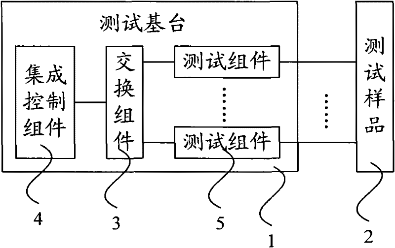
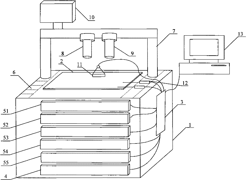
[0027] figure 1 It is a schematic diagram of the overall structure of an embodiment of the photoelectric integrated test system of the present invention, such as figure 1 As shown, the present embodiment provides an optoelectronic integrated test system, which may specifically include a test base 1 supporting a test sample 2, and the test base 1 is internally provided with an exchange component 3, an integrated control component 4, and a plurality of test components 5 . Each test component 5 inside the test base 1 is connected to the switch component 3 and the integrated control component 4 respectively, and the integrated control component 4 is used to centrally control the switch component 3 and multiple test components 5, and the multi-to-many test is realized by controlling the switch component 3 Control of a test component 5. Wherein, the test assembly 5 can be various test equipment or drive equipment in the field of liquid crystal display technology, a plurality of ...


PUM


Abstract

The invention discloses a photoelectric integrated testing system and a photoelectric testing method. The system comprises a testing base station supporting a test sample, wherein a switching component, an integrated control component and a plurality of testing components are arranged inside the testing base station; each testing component is connected with the switching component and the integrated control component; and the integrated control component is used for controlling the switching component and the testing components in a centralized manner. The invention also provides a photoelectric testing method. The invention realizes that a system can complete various photics tests and electrics tests of the same test sample at various stages, solves the problem that the test sample is required to continuously move between various testing equipment or driving equipment in the prior art, ensures the state of the test sample and the stability of the testing environment during testing, reduces the floor areas of the testing equipment or the driving equipment, saves cost and realizes intensification and efficiency of the equipment.

Description

technical field [0001] The invention relates to photoelectric testing technology, in particular to a photoelectric integrated testing system and a photoelectric testing method. Background technique [0002] With the continuous development of science and technology, liquid crystal display panels have been more and more widely used due to their advantages of thinness, lightness and small size, which save a lot of space. In the production process of liquid crystal display panels, the testing steps of liquid crystal display panels are very important, and the testing of liquid crystal display panels includes electrical testing and optical testing, such as semiconductor characteristic testing, optical testing, signal waveform testing, lighting testing, voltage Transmittance curve test and so on. Generally, the testing phase of the liquid crystal display panel is divided into three phases: module (Module) testing, unit (Cell) testing and array (Array) testing. [0003] In the pri...

Claims


Application Information

Patent Timeline
Patent Type & Authority Patents(China)
IPC IPC(8): G02F1/13
Inventor 吴昊黄婕妤
Owner BOE TECH GRP CO LTD
Learn More