Portable bus hydraulic punching machine and punching method

A punching machine and portable technology, which is applied in the installation of busbars, switchgear, electrical components, etc., can solve the problems of shallow busbar contact surface, unsmooth bolt penetration, and inability to achieve symmetrical and consistent busbar connections.

Inactive Publication Date: 2011-03-30
JIAXING ELECTRIC POWER BUREAU +1
View PDF4 Cites 8 Cited by
  • Summary
  • Abstract
  • Description
  • Claims
  • Application Information

AI Technical Summary

Problems solved by technology

There are more or less errors between them. When the error exceeds the tolerance range or exceeds the given margin range, it will cause the phenomenon that the bolts are not penetrated smoothly, which causes the busbar connection to fail to achieve symmetry and consistency. The direct cause of vertical, neat and beautiful requirements is also the direct cause of the stress on the side of the bolt and the shallow contact surface of the busbar

Method used


Image

  • Portable bus hydraulic punching machine and punching method
  • Portable bus hydraulic punching machine and punching method
  • Portable bus hydraulic punching machine and punching method

Examples


Embodiment 1

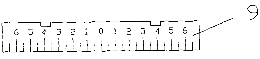
[0069] Taking the 100×10mm side of the busbar as a full circle, four round holes (50×4) need to be punched as an example to illustrate the vertical alignment method, such as Figure 6 , 7 As shown, the specific steps are as follows:

[0070] (1) Make a mark 100mm from the center of the first round hole;

[0071] (2) Use a steel square to draw a straight line perpendicular to the side of the busbar at the marked place;

[0072] (3) Align this straight line with the 100mm right side of scale 1 4, put the busbar and scale 1 4 inwardly and moderately close to the scale motherboard, and punch the first round hole;

[0073] (4) Align this straight line with the 50mm right side of scale 1 4, put the busbar and scale 1 4 inward and close to the scale motherboard, and punch the second round hole;

[0074] (5) Reverse the busbar (or reverse the hydraulic punching machine), align the straight line at the 100mm left side of the scale 4, and put the busbar and the scale 4 inward and mod...

Embodiment 2

[0077] Take the 80×8mm copper expansion joint (the side is a straight side shape) that needs to be punched with a 40×4 round hole as an example to illustrate the plane alignment method, such as Figure 8 , 9 As shown, the specific steps are as follows:

[0078] Step 1: Make a mark at a distance of about 20mm from the outer edge of the copper expansion joint connecting the copper plate, and use a steel square to draw a straight line perpendicular to the side of the marked position;

[0079] Step 2: Based on the drawn straight line, align with the 0 point of the scale, and make the copper plate part and the scale two vertically close to the scale mother board, and punch the first round hole;

[0080] Step 3: Align the straight line with 40mm on the right side of the scale, put the copper plate part and the scale two inward and close to the scale mother plate vertically, and punch the second round hole.

[0081] Step 4: Reverse the copper expansion joint (or reverse the hydraulic...


PUM


Abstract

The invention discloses a portable bus hydraulic punching machine and a punching method. The hydraulic punching machine at least comprises a hydraulic punching machine main body, a hydraulic punching machine bottom plate, a scale mother blank side bracket, a movable scale set I, a movable scale set II, a scale mother blank for positioning scales, and a protective upright post; a perforated fixed hydraulic punching machine and the scale mother blank side bracket are arranged on the hydraulic punching machine bottom plate; after supporting and accurately positioning the scale mother blank, the scale mother blank side bracket properly prolongs the length of the scale mother blank to the positive direction of the hydraulic punching machine main body, and keeps the height of the scale mother blank accordant with the punching plane of a hydraulic punching machine static impact mill; the scale mother blank is provided with two inverse trapezoidal positioning tenons for accurately positioningthe scale set I or the scale set II; and the scale set I is used for a vertical alignment method, and the scale set II is used for a planar alignment method. The portable hydraulic punching machine punches a bus based on the punching requirement of a bus connection form by using a scale I or a scale II with graduation as a reference of a bus punching circle center.

Description

technical field [0001] The invention relates to a rectangular busbar hydraulic punching machine and a punching method thereof, which are suitable for punching rectangular busbars of a portable hydraulic punching machine and belong to power generation (thermal power, hydropower), transformation, power supply, and power distribution. technology field. Background technique [0002] Busbar (the busbar referred to in this article refers to the rectangular busbar whose cross section complies with the national standard GB / T 5585.1-2005, "Regulations on Commonly Used Thickness and Width Deviations of Copper and Copper Alloy Busbars", The same below) punching is a very important link in the installation of power equipment (for the requirements for the lap connection of rectangular busbars, the national standard GBJ149-90 has made clear specification requirements, that is, when the busbars are lapped The form and size of the drilling hole and the bolt specifications used are specifie...

Claims


Application Information

Patent Timeline
Patent Type & Authority Applications(China)
IPC IPC(8): H02B3/00H02G5/00B21D28/24
Inventor 张磊
Owner JIAXING ELECTRIC POWER BUREAU
Why Eureka
Try Eureka