Motor constant-speed forward/reverse rotation control circuit

A control circuit, forward and reverse technology, applied in excitation or armature current control, motor generator/starter, starter of a single DC motor, etc., can solve the problem of cumbersome control circuits, inoperable circuits, complicated circuits, etc. problems, to achieve the effect of low cost, few components and high stability

Active Publication Date: 2014-08-20
SAKURA BATH & KITCHEN PRODS CHINA
View PDF6 Cites 7 Cited by
  • Summary
  • Abstract
  • Description
  • Claims
  • Application Information

AI Technical Summary

Problems solved by technology

[0002] The forward and reverse control circuits of existing DC motors are mainly controlled by more triodes, using more devices, and the circuit is more complicated. As long as one of the components is damaged, the entire circuit will not work, and the constant speed control circuit is usually used to adjust the voltage of the motor. Or change the multi-winding motor coil taps to adjust the speed. This control method is cumbersome and does not save energy.

Method used


Image

  • Motor constant-speed forward/reverse rotation control circuit

Examples


Embodiment

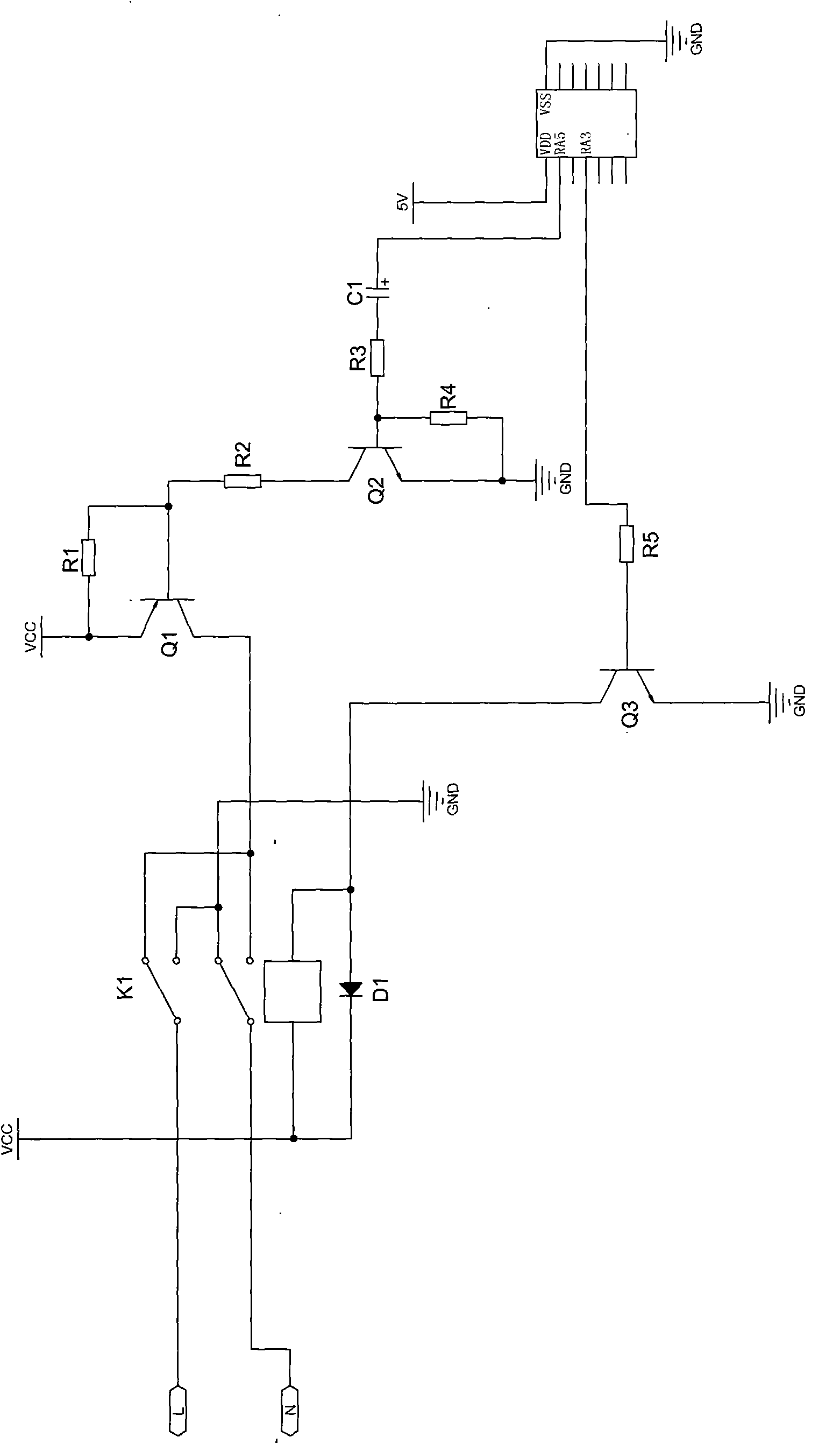
[0021] Embodiment: A constant speed forward and reverse control circuit for a motor, including a main chip U1, first, second and third transistors Q1, Q2, Q3 and an electromagnetic relay K1, the base of the third transistor Q3 passes through the fifth The resistor R5 is connected to the control signal output pin RA3 of the main chip U1, the control signal output pin RA3 outputs the forward and reverse control signals of the motor, the emitter of the third transistor Q3 is grounded to GND, and the third transistor Q3 The collector of Q3 is connected to the power supply VCC through the electromagnetic relay K1, and the electromagnetic relay K1 is provided with at least the first and second movable contacts corresponding to the motor positive pole L and the motor negative pole N; the electromagnetic relay K1 corresponds to the first movable contact The normally closed contact is connected to the collector of the first transistor Q1, and its corresponding normally open contact is g...


PUM


Abstract

The invention discloses a motor constant-speed forward / reverse rotation control circuit. A control signal output pin of a master chip outputs motor forward / reverse rotation control signals to the base electrode of a third crystal triode, the collector electrode of the third crystal triode is connected with a power source by an electromagnetic relay, and the electromagnetic relay is provided with at least a first moving contact and a second moving contact which are correspondingly communicated with the positive pole and the negative pole of the motor; the normally closed contact of the electromagnetic relay corresponding to the first moving contact is connected with the collector electrode of a first crystal triode, and the corresponding normally open contact is earthed; the normally closed contact of the electromagnetic relay corresponding to the second moving contact is earthed, and the corresponding normally open contact is connected with the collector electrode of the first crystal triode; and the base electrode of the first crystal triode is connected with the collector electrode of a second crystal triode, and a modulation signal output pin of the master chip outputs PWM signals to the base electrode of the second crystal triode. By controlling the electromagnetic relay based on the motor forward / reverse rotation control signals to realize the forward / reverse rotation of the motor and determining the rotation speed of the motor based on PWM signals, the invention has the advantages of high stability and low failure rate.

Description

technical field [0001] The invention relates to a motor control circuit, in particular to a motor constant speed forward and reverse control circuit. Background technique [0002] The forward and reverse control circuits of existing DC motors are mainly controlled by more triodes, using more devices, and the circuit is more complicated. As long as one of the components is damaged, the entire circuit will not work, and the constant speed control circuit is usually used to adjust the voltage of the motor. Or change the multi-winding motor coil taps to adjust the speed. This control method is cumbersome and does not save energy. Contents of the invention [0003] In order to overcome the above defects, the present invention provides a motor constant speed forward and reverse control circuit, the control circuit can more stably set the motor speed and control the motor forward and reverse, the circuit uses fewer components and lower cost. [0004] The technical scheme that th...

Claims


Application Information

Patent Timeline
Patent Type & Authority Patents(China)
IPC IPC(8): H02P7/28H02P1/22
Inventor 廖金柱
Owner SAKURA BATH & KITCHEN PRODS CHINA
Why Eureka
Try Eureka