Radiating device

A heat dissipation device and heat sink technology, which is applied in cooling/ventilation/heating transformation, printed circuit components, electrical components, etc., can solve the problems of ordinary optical modules that cannot be plugged and unplugged for heat dissipation, and achieve the effect of close contact

Inactive Publication Date: 2011-03-30
HUAWEI TECH CO LTD
View PDF0 Cites 24 Cited by
  • Summary
  • Abstract
  • Description
  • Claims
  • Application Information

AI Technical Summary

Problems solved by technology

[0010] The purpose of the embodiments of the present invention is to provide a heat dissipation device to solve the problems of unpluggable and poor heat dissipation of ordinary optical modules in the prior art

Method used


Image

  • Radiating device
  • Radiating device
  • Radiating device

Examples


Embodiment Construction

[0022] In order to make the above objects, features and advantages of the embodiments of the present invention more comprehensible, the embodiments of the present invention will be further described in detail below in conjunction with the accompanying drawings and specific implementation methods.

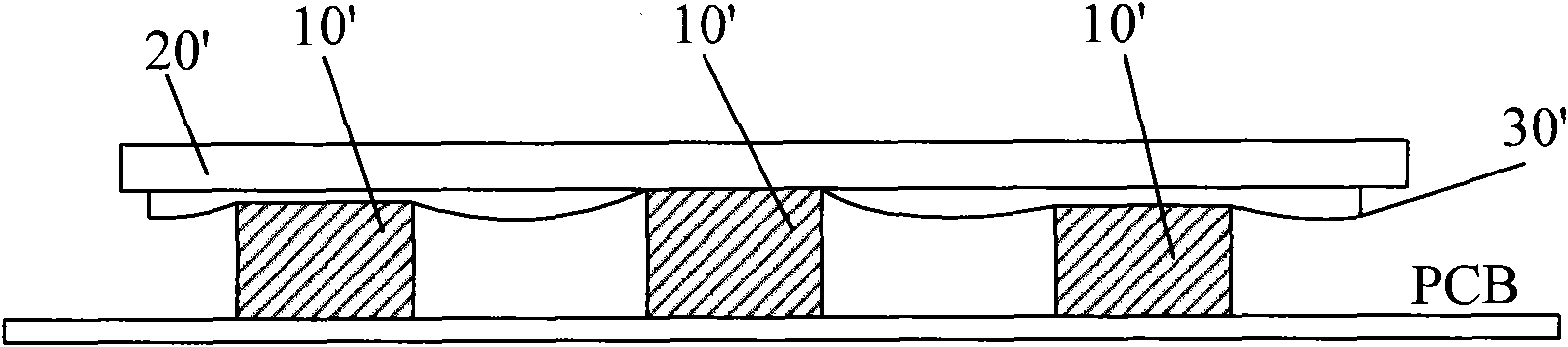
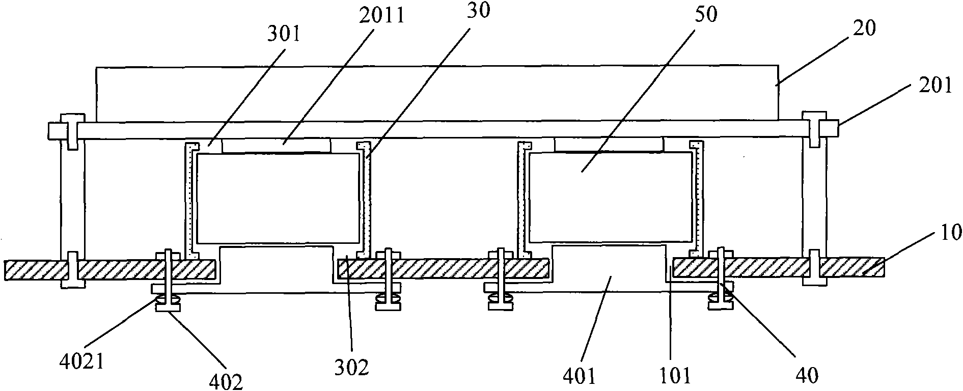
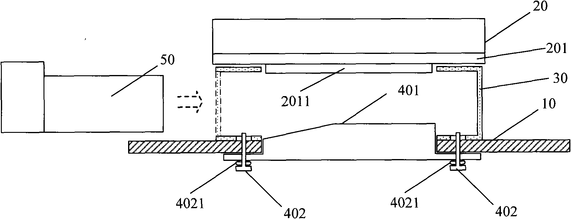
[0023] The embodiment of the present invention provides a heat dissipation device, such as figure 2 As shown, the heat dissipation device is arranged on the printed circuit board PCB10, and the PCB10 is fixed with at least two optical module housings 30, and the heat dissipation device includes a heat sink 20 and corresponding to at least two optical module housings 30 on the PCB10. Compression structure 40.

[0024] The PCB 10 is provided with at least two through holes 101 , and for the convenience of users, the plurality of through holes 101 on the PCB 10 are preferably arranged in parallel in sequence.

[0025] An upper window 301 and a lower window 302 are respectively opened...


PUM


Abstract

The embodiment of the invention discloses a radiating device. The radiating device is arranged on a printed circuit board (PCB) which is fixedly provided with at least two optical module shells, and comprises a radiator and a pressing structure, wherein the PCB is provided with through holes; the upper surface and lower surface of each optical module shell are respectively provided with an upper window and a lower window; the lower windows are matched with the through holes on the PCB; the pressing structure comprises fixing pieces and pressing blocks which are connected at the bottom of the PCB through the fixing pieces; part of the pressing blocks pass through the through holes of the PCB and the lower windows of the optical module shells and are elastically pressed against the inner spaces of the optical module shells to contact the lower surfaces of optical modules; the radiator comprises a radiating substrate which covers the optical module shells and is fixed on the PCB; the radiating substrate corresponding to the optical module shells is provided with bosses which pass through the upper windows and protrude in the inner spaces of the optical module shells to contact the upper surfaces of the optical modules; and the distance between the bosses and the pressing blocks is smaller than the height of the optical modules. Through the radiating device in the embodiment of the invention, the optical modules are convenient to insert and pull and timely radiate heat.

Description

technical field [0001] The invention relates to the technical field of electronic communication, in particular to a heat dissipation device. Background technique [0002] As electronic equipment integrates more and more functions, the power consumption on its internal PCB (Printed Circuit Board, printed circuit board) is also increasing. The heat dissipation capability of some key components and modules determines whether the function of electronic equipment can be further improvement. [0003] The XFP (10 Gigabit Small Form Factor Pluggable, 10G small-size pluggable) optical module used in electronic equipment is an integrated optical transceiver module (XFP optical modules are referred to as optical modules in the following), which realizes optical-electrical Active optoelectronic devices for conversion and electro-optical conversion are important functional modules in communication equipment such as transmission and access. With the continuous improvement of key technic...

Claims


Application Information

Patent Timeline
Patent Type & Authority Applications(China)
IPC IPC(8): H05K7/20H05K1/02H01L23/40
Inventor 杨右权孔小明杨正东
Owner HUAWEI TECH CO LTD
Why Eureka
Try Eureka