Machine tool for grinding composite workpiece under tensioning state

A technology for machining machine tools and workpieces, applied in the field of grinding compound machine tools, can solve problems such as low efficiency and many clamping times, improve machining accuracy, reduce geometric tolerances such as radial runout and roundness, and enhance rigidity. Effect

Inactive Publication Date: 2011-04-06
赵显华
View PDF3 Cites 22 Cited by
  • Summary
  • Abstract
  • Description
  • Claims
  • Application Information

AI Technical Summary

Problems solved by technology

[0004] The present invention aims at the problems of many times of clamping, low efficiency and multiple clampings existing in the existing multi-process processing technology for the surface of shaft workpieces, and provides a high-efficiency, precision-guaranteed machining of the turning-grinding composite workpiece under tension machine tool

Method used


Image

  • Machine tool for grinding composite workpiece under tensioning state
  • Machine tool for grinding composite workpiece under tensioning state
  • Machine tool for grinding composite workpiece under tensioning state

Examples


Embodiment Construction

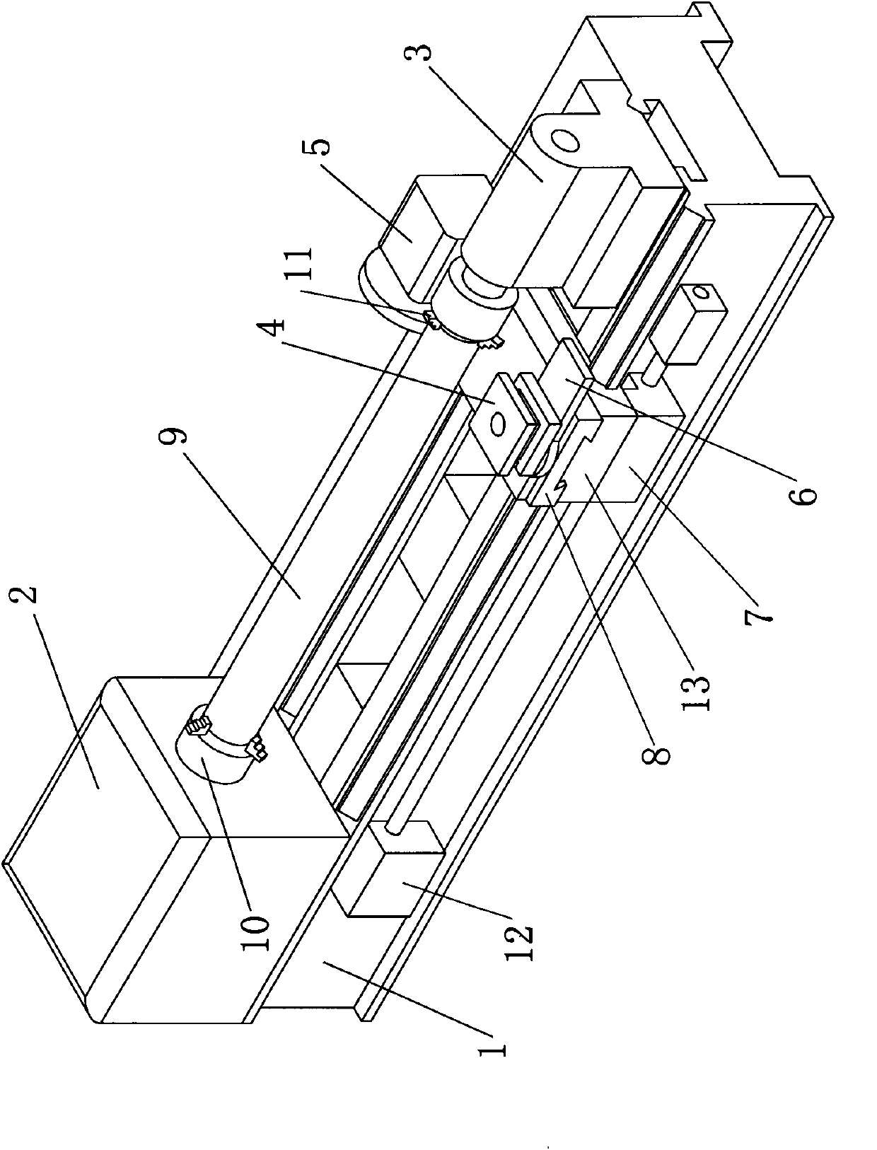
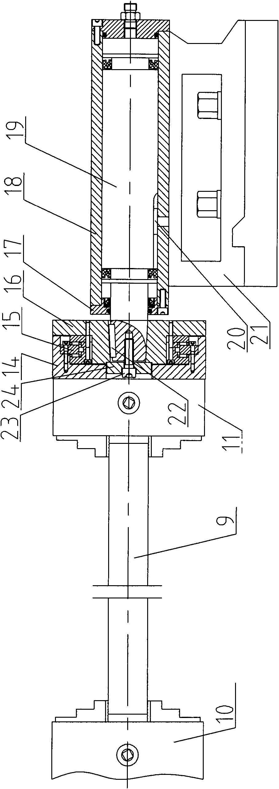
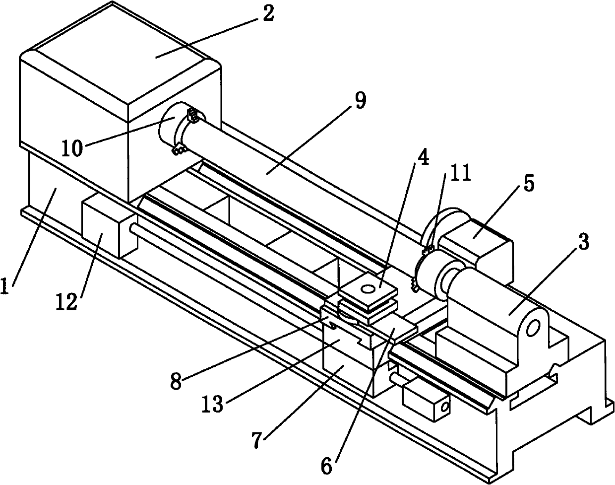
[0014] Such as figure 1 As shown, the processing machine tool under the tensed state of the turning-grinding composite workpiece of the present invention is to increase the grinding device 5 and the tailstock tensioning device 3 on the basis of the existing lathe, mainly including the bed 1, the headstock 2, the feeder Giving box 12, slide board box 7, large plank 13, knife rest 4 and grinding device 5 and tailstock tensioning device 3. Same as the existing ordinary lathes, the bed 1 is equipped with a bedside box 2, a feed box 12, a slide box 7, a tailstock tensioning device 3 and a large carriage 13, wherein the slide box 7 is fed longitudinally The lead screw is connected with the feed box 12, the large carriage 13 is installed on the bed 1 through two longitudinal guide rails, and is rigidly connected with the slide box 7 through bolts, the middle carriage 8 is installed on the large carriage 13 through the dovetail guide rails and is connected with the large carriage 13 ...


PUM


Abstract

The invention provides a machine tool for grinding a composite workpiece under the tensioning state. The machine tool comprises a machine tool, a grinding device and a tailstock tensioning device, wherein the grinding device is arranged at one end of a carriage opposite to a knife rest in the machine tool and is connected with a feeding mechanism on the carriage; and the tailstock tensioning device is arranged on the rear of a machine tool body. The machine tool can finish turning and grinding axial workpieces, and can effectively reduce radial runout, circular degree and other form and position tolerances of the workpiece and improve the machining accuracy by adopting a clamping mode under the tensioning state.

Description

technical field [0001] The invention relates to a grinding compound machine tool for turning the surface of shaft and pipe workpieces, which belongs to the technical field of mechanical processing equipment. Background technique [0002] The surface processing equipment for shaft workpieces usually includes lathes and grinders, etc. These equipments can only perform one function. Between transfers, the workpiece has to go through multiple clamping. In this way, not only the production efficiency is low, but also the clamping positioning datum will change after each clamping, especially for some slender shafts and thin-walled tube parts during the processing process, if the datum is changed in the second clamping Change, the processing of the next process will destroy the state after the processing of the previous process, and the processing positioning reference of the workpiece will change, making it difficult for the processed parts to meet the design requirements. [00...

Claims


Application Information

Patent Timeline
Patent Type & Authority Applications(China)
IPC IPC(8): B23P23/02B23B23/00
Inventor 赵显华王爱福鞠远明
Owner 赵显华
Why Eureka
Try Eureka