Gear spindle structure for horizontal type machining center

A gear and spindle technology, applied in metal processing equipment, metal processing machinery parts, manufacturing tools, etc., can solve the problems of limited spindle rotation speed, limited use range, low production efficiency, etc., to reduce the overall size and weight, use Wide-ranging, high-efficiency effects

Inactive Publication Date: 2011-04-06
DALIAN HUAGEN MACHINERY
View PDF12 Cites 7 Cited by
  • Summary
  • Abstract
  • Description
  • Claims
  • Application Information

AI Technical Summary

Problems solved by technology

The speed of the existing gear spindle with a torque of 2000 (Nm) or more is below 4500 (rev / min), which limits the use range of the machining center as a general-purpose processing equipment, and the production efficiency is low
The reason is that the gear spindle with large torque (above 2000Nm) generally adopts a gear transmission scheme with a large reduction ratio. The rotation speed of the main shaft is limited. At present, when the diameter of the main shaft bearing is 110mm, the maximum speed of the main shaft with grease lubrication is below 4500 rpm. Therefore, the existing gear main shaft structure has low working efficiency and limited application range.

Method used


Image

  • Gear spindle structure for horizontal type machining center
  • Gear spindle structure for horizontal type machining center

Examples


Embodiment Construction

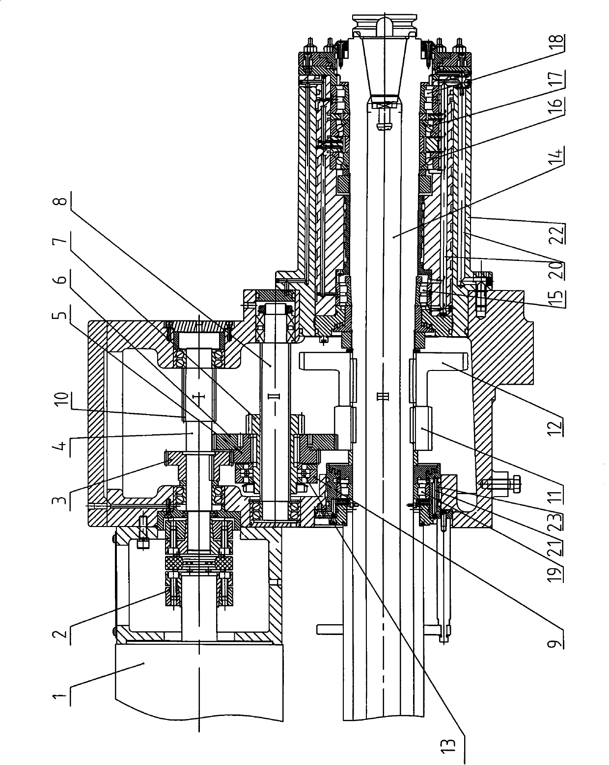
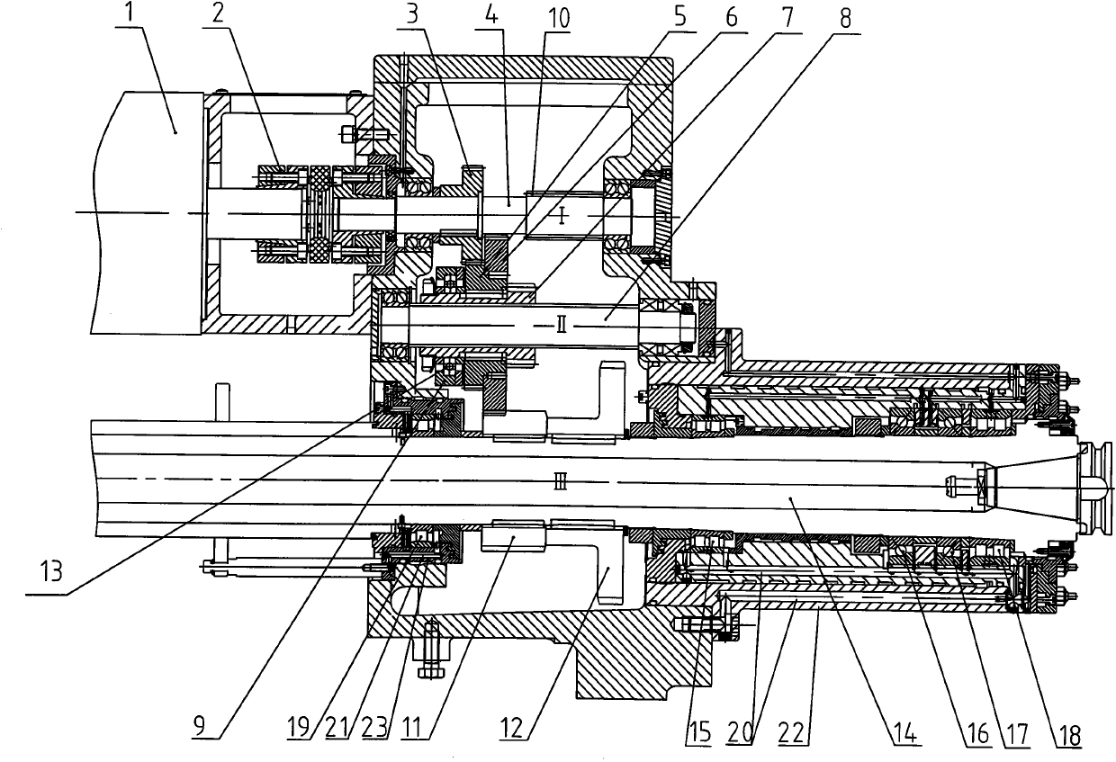
[0008] As shown in the figure: 4 is a driving shaft, 8 is an intermediate shaft, and 14 is a main shaft, all of which are supported on the main shaft housing through bearings, and the above-mentioned three shafts are arranged parallel to each other. The left end of the driving shaft 4 is connected with the motor 1 through a shaft coupling 2 . The first gear 3 of the driving shaft is connected with the key on the driving shaft 4, and the second gear 10 of the driving shaft is processed on the driving shaft 4;

[0009] On the main shaft 14, the first main shaft gear 11 and the second main shaft gear 12 are keyed;

[0010] On the intermediate shaft 8, the third intermediate shaft gear 7 which can move axially is connected with the spline mode. The first countershaft gear 5 and the second countershaft gear 6 make the first countershaft gear 5 , the second countershaft gear 6 and the third countershaft gear 7 fixed in one structure and can slide axially along the countershaft 8 . ...


PUM


Abstract

The invention relates to a gear spindle structure for a horizontal type machining center, which comprises a spindle box body, a driving shaft, an intermediate shaft and a spindle, wherein the driving shaft, the intermediate shaft and the spindle are supported on the spindle box body in parallel; a first gear of the driving shaft and a second gear of the driving shaft are fixed on the driving shaft; a first gear of the spindle and a second gear of the spindle are fixed on the spindle; a first gear of the intermediate shaft, a second gear of the intermediate shaft and a third gear of the intermediate shaft, which are capable of axially sliding along the intermediate shaft and are mutually connected to form an integrate are arranged on the intermediate shaft; the first gear of the driving shaft can be engaged with the first gear of the intermediate shaft; the second gear of the intermediate shaft can be engaged with the first gear of the spindle and the second gear of the driving shaft; the third gear of the intermediate shaft can be engaged with the second gear of the spindle; and the first gear of the intermediate shaft, the second gear of the intermediate shaft and the third gear of the intermediate shaft are connected to a push type shifting fork of a cylinder through a shifting fork bearing. The spindle has the advantages that the highest rotating speed is enhanced; the work efficiency is high; and the use range is wide.

Description

technical field [0001] The invention relates to a gear shaft transmission type main shaft structure, in particular to a gear main shaft structure for a horizontal machining center. Background technique [0002] The existing spindles used in machining centers are mainly in the form of electric spindles and gear spindles. The electric spindles can achieve high speed, and the gear spindles can achieve high power and high torque. The speed of the existing gear spindle with a torque above 2000 (Nm) is below 4500 (rev / min), which limits the scope of use of the machining center as a general-purpose processing equipment, and the production efficiency is low. The reason is that the gear spindle with large torque (above 2000Nm) generally adopts a gear transmission scheme with a large reduction ratio. The rotation speed of the main shaft is limited. At present, when the diameter of the main shaft bearing is 110mm, the maximum speed of the grease-lubricated main shaft is below 4500 rpm...

Claims


Application Information

Patent Timeline
Patent Type & Authority Applications(China)
IPC IPC(8): B23Q5/04B23B19/02
Inventor 马骋周晓宇李凯邵连英闫雪峰王世鹏
Owner DALIAN HUAGEN MACHINERY
Why Eureka
Try Eureka