Rotor, motor and electric vehicle

A rotor and rotor shaft technology, applied in the field of electric vehicles, can solve the problems of loss of motor kinetic energy, low rotor iron consumption, limited heat generation, etc., and achieve the effect of reducing kinetic energy loss and effective heat dissipation

Active Publication Date: 2019-10-25
HUAWEI DIGITAL POWER TECH CO LTD
View PDF4 Cites 5 Cited by
  • Summary
  • Abstract
  • Description
  • Claims
  • Application Information

AI Technical Summary

Problems solved by technology

However, when the motor is running at low speed, the iron consumption of the rotor is low and the calorific value is limited, so it is not necessary to dissipate heat from the rotor. Lost part of the kinetic energy of the motor

Method used


Image

  • Rotor, motor and electric vehicle
  • Rotor, motor and electric vehicle
  • Rotor, motor and electric vehicle

Examples


Embodiment Construction

[0041] In order to make the purpose, technical solution and advantages of the application clearer, the application will be further described in detail below in conjunction with the accompanying drawings.

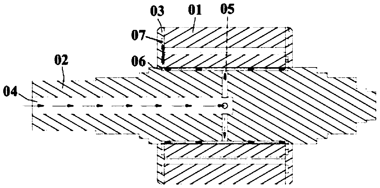
[0042] In view of the poor heat dissipation effect caused by the water-cooled heat dissipation technology and the high requirements for structural precision, some motors are gradually adopting oil-cooled heat dissipation instead of water-cooled heat dissipation. like figure 1 The shown motor adopts oil cooling heat dissipation technology, its structure includes a rotor core 01 and a rotor shaft 02 fixedly assembled in the rotor core 01, in addition, the two ends of the rotor core 01 are respectively provided with fixing plates 03 , The fixing plate 03 is provided with a through hole through which the rotor shaft can pass. When arranging the cooling passage, one end surface of the rotor shaft 02 is provided with a blind hole 04 arranged in the axial direction, and at the sam...


PUM


Abstract

The application provides a rotor, a motor and an electric vehicle which are used for reducing the kinetic energy loss of the motor on the premise of effective heat dissipation of the rotor. The rotorincludes a rotor core and a rotor shaft, wherein, the rotor core is cylindrical and is provided with a first end and a second end; at least one end of the rotor core is fixed with a fixing plate, thefixing plate is provided with a through hole and a first flow channel, the first flow channel is a damping flow channel, an inlet of the first flow channel communicates with the through hole, and an outlet of the first flow channel is arranged on the peripheral side surface of the fixing plate; the rotor shaft is fixedly assembled in the rotor core, at least one end of the rotor shaft extends to the outer side of the rotor core from the through hole of the fixing plate, a second flow channel arranged in the axial direction and a third flow channel arranged in the radial direction at least at the position corresponding to one of the through holes are arranged in the rotor shaft, the inlet of the second flow channel is arranged at one end of the rotor shaft, the outlet of the second flow channel communicates with the inlet of the third flow channel, and the outlet of the third flow channel communicates with the inlet of the first flow channel.

Description

technical field [0001] The present application relates to the technical field of mechanical equipment, in particular to a rotor, a motor and an electric vehicle. Background technique [0002] In the prior art, motors mostly use water-cooling heat dissipation technology for heat dissipation. However, the power density of water-cooling heat dissipation is low, and because the cooling water has no insulation, it cannot directly contact with the components of the motor, which leads to link heat in the cooling path. The resistance is large, and the heat dissipation effect is not good; at the same time, because the water cooling heat dissipation technology requires relatively high structural precision of the components of the motor, the manufacturing cost and time cost of the motor are relatively increased. In order to overcome the above problems, some motors are currently using oil cooling instead of water cooling. For the existing motors using oil-cooled heat dissipation techno...

Claims


Application Information

Patent Timeline
Patent Type & Authority Applications(China)
IPC IPC(8): H02K1/32H02K9/19
CPCH02K1/32H02K9/19Y02T10/64H02K7/006B60K1/00B60K17/08B60K2001/006H02K1/28
Inventor 王健刚李泉明谢廷裕
Owner HUAWEI DIGITAL POWER TECH CO LTD
Why Eureka
Try Eureka