Piston for a cylinder of a combustion engine

a technology for combustion engines and pistons, which is applied in the direction of pistons, combustion engines, machines/engines, etc., can solve the problems of reducing thermodynamic efficiency, reducing the thermodynamic efficiency, and causing high soot formation

Active Publication Date: 2018-08-28
VOLVO LASTVAGNAR AB
View PDF16 Cites 7 Cited by
  • Summary
  • Abstract
  • Description
  • Claims
  • Application Information

AI Technical Summary

Benefits of technology

[0009]The present invention is based on the insight that during ignition in a cylinder of an internal combustion engine a flame that impinges the side section below the at least one recess will not only be directed towards the ridges, but will also be directed in an upward direction towards the cylinder liner. By providing a recess in the piston crown, a majority of the part of the flame directed towards the cylinder liner will instead become directed towards the cylinder head and thereafter back towards the centre of the cylinder. An advantage of the invention is, at least, that a reduction of soot emissions is provided for the internal combustion engine in which the piston is positioned, since the combination of a ridge and a recess increases the amount of the flame directed back towards the centre of the cylinder. Also, by providing a recess in accordance with the present invention enables for a reduction of a spray axis angle, i.e. the angle of which the spray is injected into the cylinder, which will be further described below. A reduction of the spray axis angle provides for an improved combustion process of the combustion chamber in the cylinder, since a larger amount of the flame will be directed towards the ridges and thereby be directed towards the centre of the cylinder which reduces the loss of kinetic energy of the flame. The recess will also direct the upwardly portion of the flame towards the centre of the cylinder.
[0010]The present invention is directed towards pistons which are configured to be arranged in internal combustion engines with no, or low, swirling effect during operation. The ratio of swirl in an internal combustion engine is a ratio of the tangential velocity of the air spinning around the combustion chamber divided by the engine speed. Accordingly, the swirl ratio is a measure of the tangential motion of air as it enters the engine cylinder from induction ports of the cylinder head. The swirl ratio of the present invention is below 0.7 which is considered to be low swirl.
[0011]The wording “upper surface” should be interpreted as the surface of the piston which is, when the piston is positioned in a cylinder of a combustion chamber, faces the cylinder head and hence being the part of the piston located closest to the cylinder head. Similarly, the wording “upwardly facing” should thus be interpreted as facing the cylinder head when the piston is mounted in the cylinder. The wording “upper” and “upwardly” hence correspond to the direction away from an engine crank shaft when the piston is positioned in a cylinder.
[0012]According to an example embodiment of the present invention, ridges and recesses may be formed alternatingly in the circumferential direction of the side section.
[0013]According to an example embodiment of the present invention, the at least one recess may be positioned at an equal distance from its closest ridges.
[0014]Hereby, the ridges are arranged symmetrically in relation to the at least one recess. The flame will thus impinge the side section and be directed not only to the recess, but towards each of the adjacent ridges. The flame will, due to the equal distance between the at least one recess and the respective ridges, reach each of the adjacent ridges at an approximately equal point in time.

Problems solved by technology

Combustion with fuel, i.e. rich, fuel / air mixture with poor mixing at high temperature produces high soot formation.
However, the percentages can rise if unburnt fuel ends up in relatively cool regions.
Further, controlling the flame in accordance with the above, the combustion process may be executed more optimal, which is beneficial in relation to combustion executed “too late” in a cycle, as this reduces the thermodynamic efficiency.

Method used


Image

  • Piston for a cylinder of a combustion engine
  • Piston for a cylinder of a combustion engine
  • Piston for a cylinder of a combustion engine

Examples


Embodiment Construction

[0035]The present invention will now be described more fully hereinafter with reference to the accompanying drawings, in which an exemplary embodiment of the invention is shown. The invention may, however, be embodied in many different forms and should not be construed as limited to the embodiment set forth herein; rather, this embodiment is provided for thoroughness and completeness. Like reference character refer to like elements throughout the description.

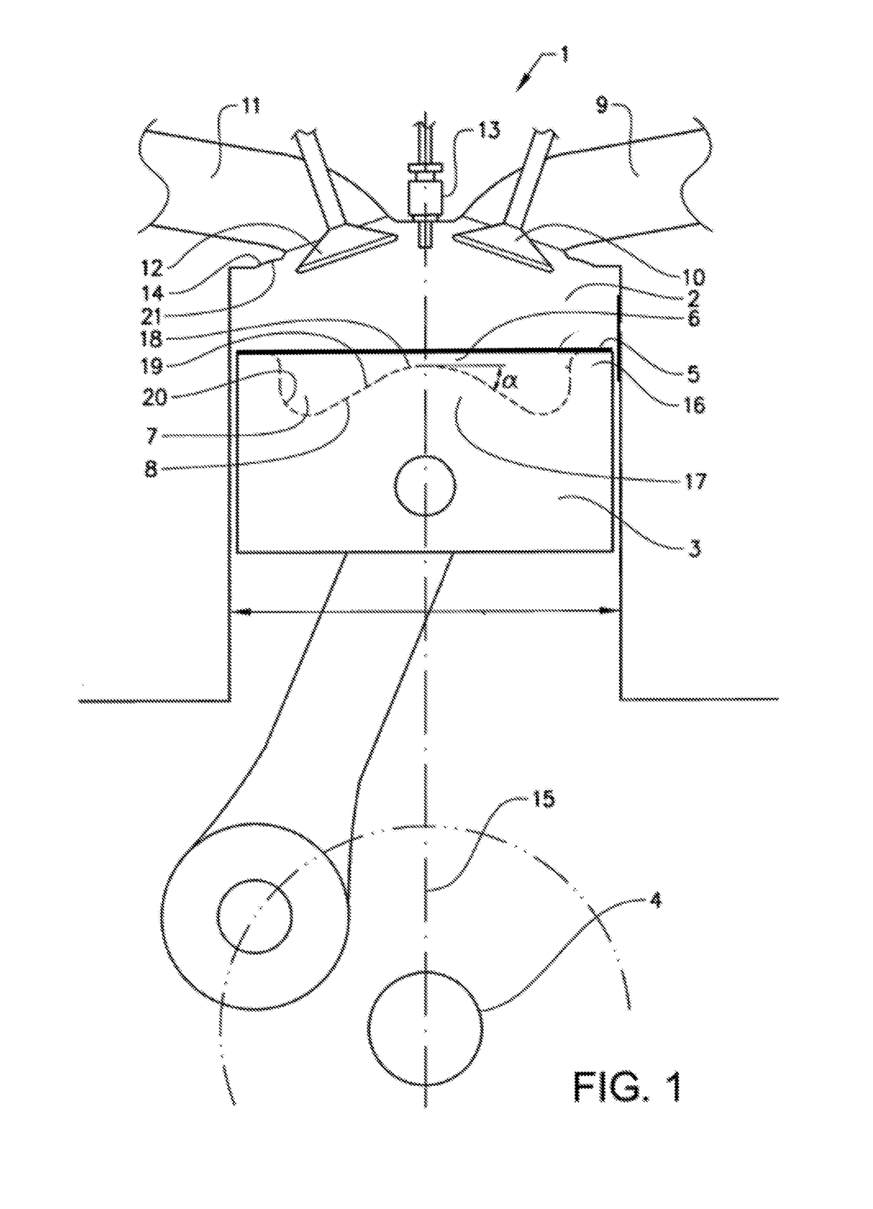
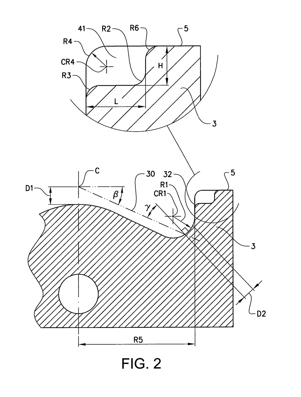
[0036]Firstly, attention is drawn to FIG. 1 which illustrates the inventive piston 3 arranged in a cylinder 2 of an internal combustion engine 1. To understand the unique physical characteristics of the combustion provided by means of the inventive piston 3, FIGS. 1 and 2 illustrates the various physical characteristics or parameters provided in a cylinder arrangement and in the inventive piston 3. Hence, FIG. 1 will incorporate a description of the combustion process including parameters of both the inventive piston 3 as well a...


PUM


Abstract

A piston for a cylinder of a combustion engine includes piston crown including a piston bowl formed by an upwardly facing cavity, the piston bowl including a floor section with a central, and a side section, the side section connecting the inner section with an upper surface of the piston crown, wherein the side section is formed with mutually spaced apart ridges protruding towards the apex, and wherein the side section having at least one recess at an upper end of the side section connecting the side section with the upper surface of the piston crown.

Description

BACKGROUND AND SUMMARY[0001]The present invention relates to a piston. In more detail, the present invention relates to a piston for use in a cylinder of an internal combustion engine, wherein the shape of the piston reduces the soot emissions of the internal combustion engine.[0002]Soot particles, or particulates, are a product which, during combustion, can be formed and subsequently oxidized into carbon dioxide, CO2.[0003]Combustion with fuel, i.e. rich, fuel / air mixture with poor mixing at high temperature produces high soot formation. If the formed soot particles can be brought together with oxidizing substances such as e.g. oxygen atoms, oxygen molecules, hydroxide at sufficiently high temperature for a good oxidation rate, a greater part of the soot particles can be oxidized. In a diesel engine, the oxidation process is considered to be in the same order of magnitude as the formation, which means that net soot production is the difference between formed quantity of soot and ox...

Claims


Application Information

Patent Timeline
Patent Type & Authority Patents(United States)
IPC IPC(8): F02F3/00F02B23/06
CPCF02F3/0015F02B23/0651F02B23/0627Y02T10/125Y02T10/12
Inventor EISMARK, JAN
Owner VOLVO LASTVAGNAR AB
Why Eureka
Try Eureka