Windscreen installation driving device

A drive and wiper technology, applied in the drive field, can solve problems such as huge installation space, and achieve the effects of reducing internal friction loss, reducing shaft offset, and large output angle

Inactive Publication Date: 2011-04-06
ROBERT BOSCH GMBH
View PDF9 Cites 5 Cited by
  • Summary
  • Abstract
  • Description
  • Claims
  • Application Information

AI Technical Summary

Problems solved by technology

Here, it has proven to be disadvantageous that a large installation space is required due to the bulky worm gear and t...

Method used


Image

  • Windscreen installation driving device
  • Windscreen installation driving device
  • Windscreen installation driving device

Examples


Embodiment Construction

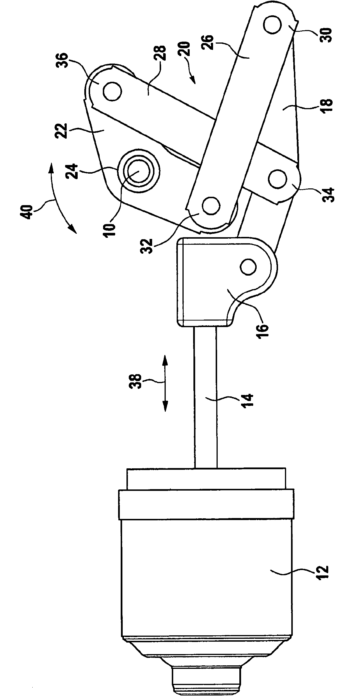
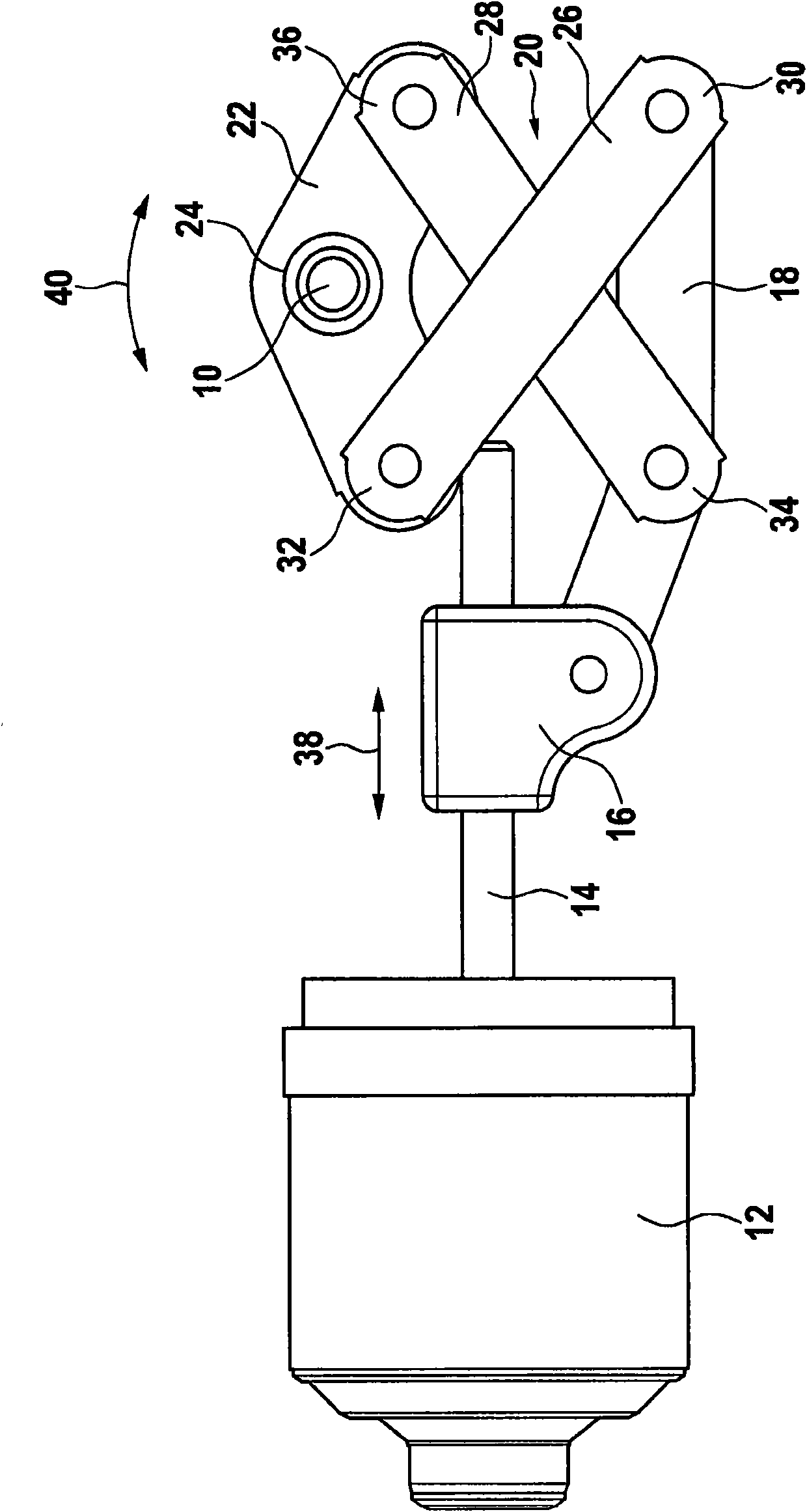
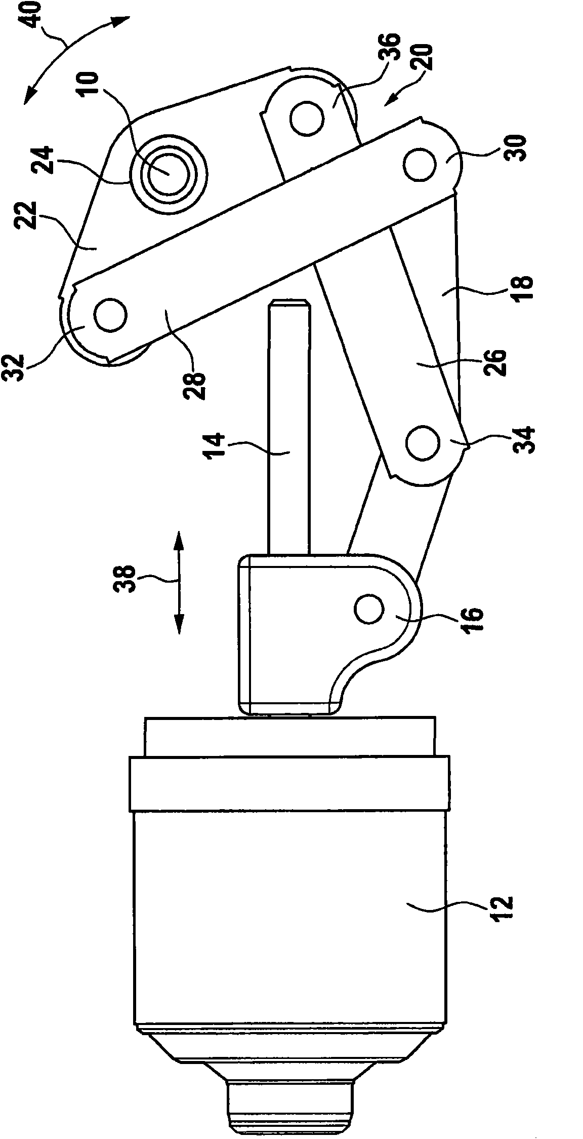
[0026] Figure 1 to 4 The drive for the wiper device according to the invention is shown for moving the output shaft 10. Here, the electric motor 12 is preferably a reversible motor driving a rotatably supported drive shaft 14 which is preferably designed as a screw thread or a worm thread. The drive shaft 14 is connected to the linear movement element 16 in a rotationally fixed manner, so that the rotational movement of the drive shaft 14 can be converted into the linear movement of the linear movement element 16. The linear movement element 16 is connected via a coupling piece 18 arranged on the linear movement element 16 in a fixed position, wherein the coupling piece 18 is articulated with the swing arm 22 via a fork guide 20, wherein the swing arm 22 is connected to the swing arm 22 via a hollow bore 24 The output shaft 10 is connected.

[0027] The fork-shaped guide device 20 has a first fork-shaped guide rod 26 and a second fork-shaped guide rod 28, wherein the first for...


PUM


Abstract

The invention relates to a windscreen installation driving device, for making an output shaft (10) move, comprising a drive shaft (14) driven by a motor (12) and a linear motion element (16) integrated with the drive shaft (14) in a torque-proof manner, wherein the linear motion element (16) is connected with the output shaft (10) by a connecting piece (18) and an oscillating arm (22) integrated with the output shaft (10) in a torque-proof manner and a cross guide device (20) is arranged to mutually connect the connecting piece (18) with the oscillating arm (22) in an articulated manner.

Description

Technical field [0001] The invention relates to a drive for a wiper device for moving an output shaft. Background technique [0002] In a car with opposing wiper devices with a large front wind window, two electric wiper devices are usually used, of which a reversible motor is mainly used, which has a traditional connection between the oscillation motor and the output shaft. Rod. Thus, for example, DE 10 2006 042 322 A1 discloses a wiper device with a wiper drive and a transmission device for driving the wiper shaft, wherein the back and forth movement is generated in the wiper shaft in the following manner Rotation, that is, a worm is provided as a push rod, which is connected to the worm wheel through an eccentric and hinged connection. Here, what has been proven to be flawed is that a huge installation space is required due to the bulky worm gear and the resulting reciprocating motion of the push rod, which makes it difficult to apply flexibly in different automobile models....

Claims


Application Information

Patent Timeline
IPC IPC(8): B60S1/08B60S1/16
CPCB60S1/26B60S1/245
Inventor S·迈耶J-M·里特
Owner ROBERT BOSCH GMBH
Why Eureka
Try Eureka