Construction pushing device of steel box beam

A technology of jacking devices and steel box girders, which is applied in erecting/assembling bridges, bridge construction, bridges, etc., can solve the problems of occupying river channel structural materials, etc., and achieve the effects of good sliding ability, high durability and simple device structure

Active Publication Date: 2012-06-06
CHINA RAILWAY 24TH BUREAU GRP +1
View PDF0 Cites 0 Cited by
  • Summary
  • Abstract
  • Description
  • Claims
  • Application Information

AI Technical Summary

Problems solved by technology

When the beam needs to be replaced, the support method needs to occupy the river channel and a large amount of structural materials

Method used


Image

  • Construction pushing device of steel box beam
  • Construction pushing device of steel box beam
  • Construction pushing device of steel box beam

Examples


Embodiment Construction

[0028] The features of the present invention and other related features will be further described in detail below in conjunction with the accompanying drawings through embodiments, so as to facilitate the understanding of those skilled in the art:

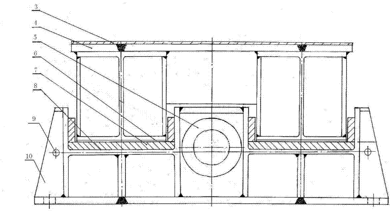
[0029] attached Figure 1-11 The marks 1-18 indicate: slide plate 1, steel box girder transverse bottom surface 2, cloth rubber plate 3, upper support plate 4, jacking force device 5, stainless steel plate 6, polytetrafluoroethylene plate 7, “U” Type slideway 8, positioning adjustment bolt 9, lower supporting plate 10, base plate 11, H-shaped steel box frame 12, pin seat 13, supporting plate 14, chute 15, rib 16, substrate plate 17, web 18.

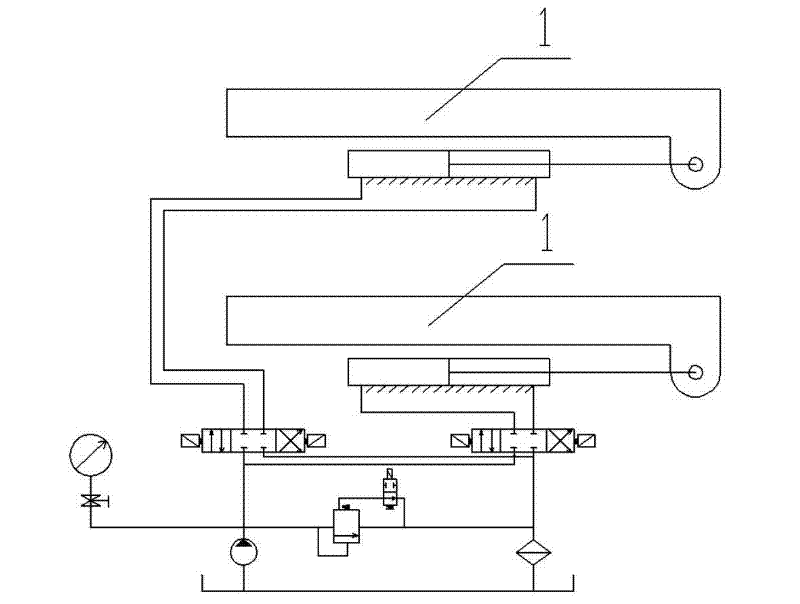
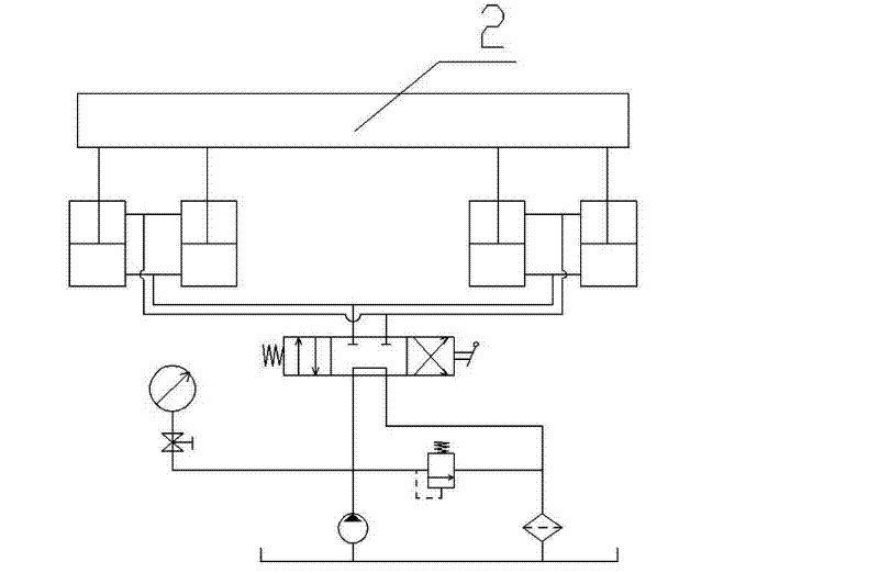
[0030] The invention is a steel box girder erection and pushing device, which is used for vertically moving a large-tonnage steel box girder, and can complete various steel-concrete structures with large spans and continuous structures in cooperation with vertical lifting and falling beam hydr...


PUM


Abstract

The invention relates to the technical field of bridge engineering construction, in particular to a sliding plate type hydraulic pushing device for a longitudinally-moved big tonnage steel box beam. The device comprises a drive pusher which mainly comprises an upper support plate, a stainless steel plate, a polyfluortetraethylene plate, a lower support plate and a pushing power device, wherein the pushing power device is arranged on the lower support plate. The upper surface of the lower support plate is provided with a U-shaped slideway; the polyfluortetraethylene plate is arranged on the U-shaped slideway; the bottom of the upper support plate is welded with the stainless steel plate, and the shape of the stainless steel plate is matched with the shape of the U-shaped slideway; and the pushing power device pushes the upper support plate to move in a reciprocation and sliding way on the U-shaped slideway. The invention has the advantages of simple structure, compact installation, high durability, no impact inertia through hydraulic pushing, small horizontal pushing force of buttress, stable pushing, no noise, no vibration and controlled pushing longitudinally-movement speed. The sliding materials are good in abrasion and sliding capability, thus a large amount of rail apparatuses and labor forces are saved.

Description

technical field [0001] The invention relates to the technical field of bridge engineering construction, in particular to a slide-type hydraulic jacking device for longitudinally moving a large-tonnage steel box girder. Background technique [0002] The construction principle of the jacking method is to set up a prefabricated field behind the platform along the longitudinal axis of the bridge, prefabricate the beam body in sections, and after the longitudinal prestressed tendons are stretched, force is applied by a horizontal jack, and the beam is moved section by section with the help of slideways and sliders. Push it forward, drop the beam after it is in place, and replace the formal support. The key of the jacking construction method is the jacking operation, the core of which is to push the beam into place with limited jacking force. At present, the jacking construction method is mainly divided into single-point jacking and multi-point jacking. The jacking force system c...

Claims


Application Information

Patent Timeline
Patent Type & Authority Patents(China)
IPC IPC(8): E01D21/06E01D2/04
Inventor 向科周迎选方秋林卢见
Owner CHINA RAILWAY 24TH BUREAU GRP
Why Eureka
Try Eureka