

Construction method of under cutting excavation supporting of of deeply buried soft-rock large tunnel
A construction method and tunnel technology, applied in tunnels, tunnel linings, earthwork drilling and mining, etc., can solve problems such as instability of surrounding rock in the upper half section, subsidence of soft rock in the upper section, bottom sag, etc., and achieve the effect of ensuring overall stability and safety
- Summary
- Abstract
- Description
- Claims
- Application Information
AI Technical Summary
Problems solved by technology
Method used
Image

Examples
Embodiment Construction
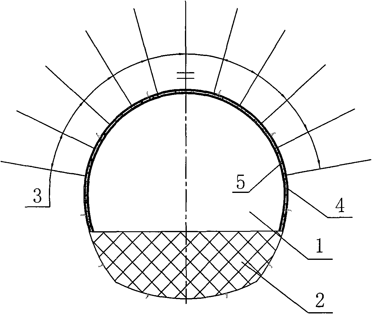
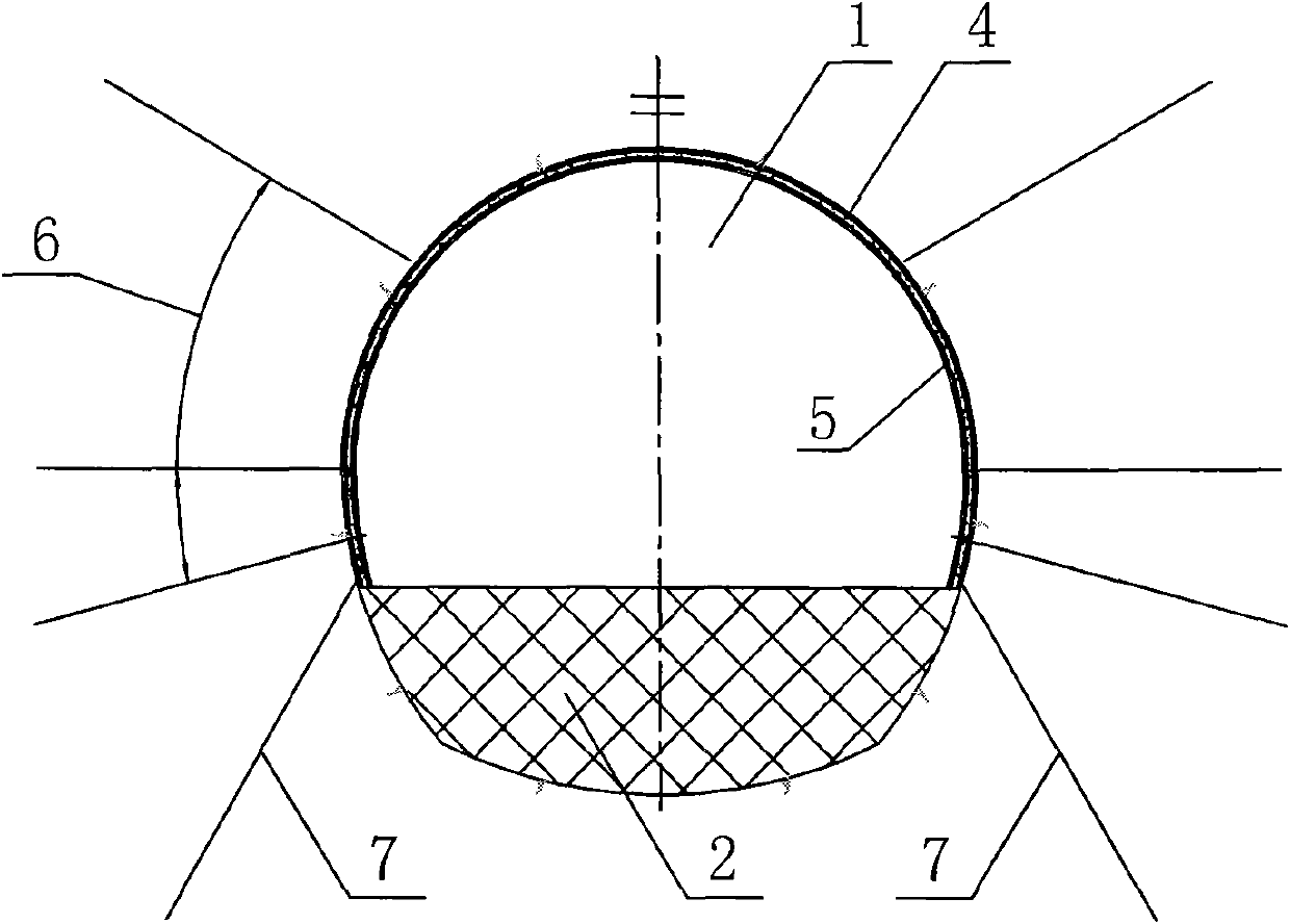
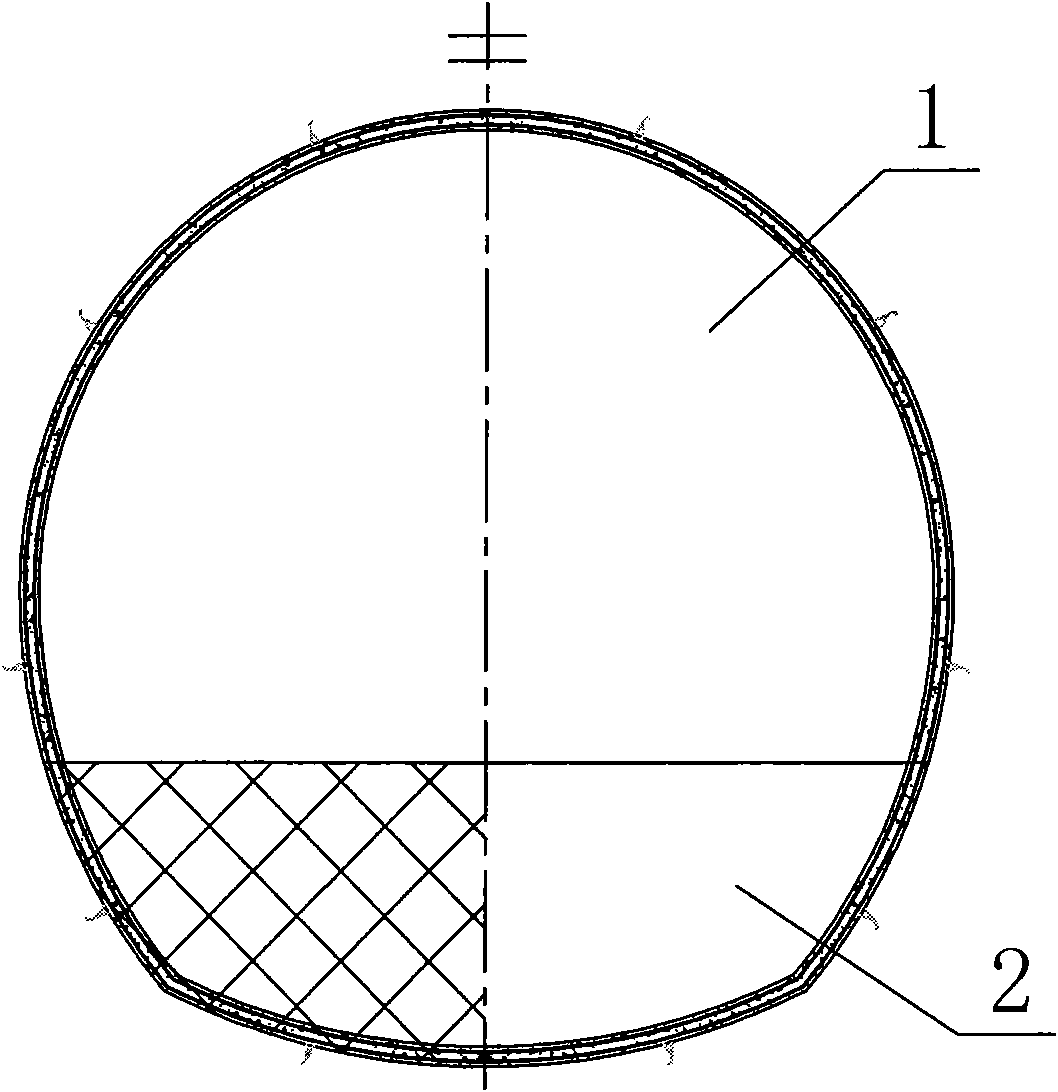
[0019] Combining with the design and construction practice of a large deep-buried soft rock tunnel in a western hydropower project, the present invention proposes to use foundation anchor piles 7 and prestressed anchor rods 6 pairs of upper and lower half-sections of the cavern before excavation of the deep soft rock large-scale tunnel Targeted pre-reinforcement is carried out, and then the left and right sections of the tunnel are excavated, the steel arch legs of the upper step cavern are connected in time, and the excavation and support design and construction of the closed full-section support arch are systematic. method to achieve the purpose of ensuring the safety and stability of the tunnel structure. The concrete construction steps of this embodiment are as follows:
[0020] a. According to the geological conditions revealed by the excavation, implement the necessary system support for the excavated upper half-section cavern 1 of the upper step of the tunnel, including...
PUM
 Abstract
Description
Claims
Application Information