Intelligent sine-wave-output uninterruptible power supply and automatic control method
An output control, sine wave technology, applied in the field of power supply, can solve the problems of heavy weight, complex circuit, poor output stability, etc.
- Summary
- Abstract
- Description
- Claims
- Application Information
AI Technical Summary
Problems solved by technology
Method used
Image
Examples
Embodiment 1
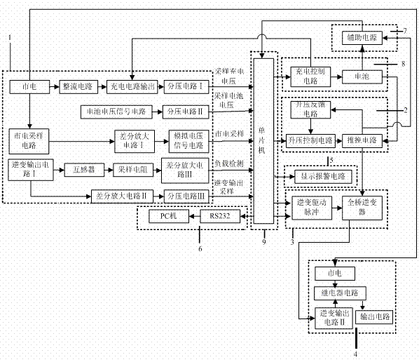
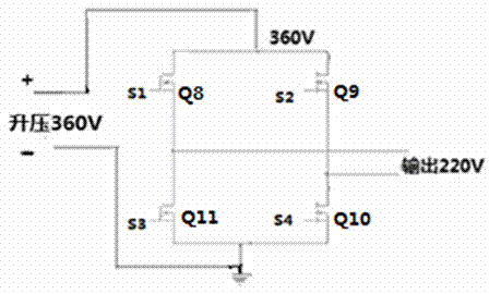
[0088] Embodiment 1: as Figure 1-9 As shown, an intelligent sine wave output uninterruptible power supply, including sampling detection circuit 1, boost circuit 2, inverter circuit 3, output control circuit 4, display alarm circuit 5, communication circuit 6, auxiliary power supply circuit 7, charging Control circuit 8, single-chip microcomputer 9; wherein single-chip microcomputer 9 is connected with sampling detection circuit 1, boost circuit 2, inverter circuit 3, output control circuit 4, display alarm circuit 5, communication circuit 6, auxiliary power supply circuit 7, and charging control circuit 8 , the boost circuit 2 is connected to the auxiliary power supply circuit 7 and the inverter circuit 3 , and the inverter circuit 3 is connected to the output control circuit 4 .
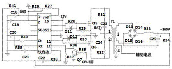
[0089] The boost circuit 2 includes a boost control circuit, a push-pull circuit, and a boost feedback circuit; wherein the boost control circuit is connected to the push-pull circuit, the push-pul...
Embodiment 2
[0129] Embodiment 2: as Figure 1-9 As shown, an intelligent sine wave output uninterruptible power supply, including sampling detection circuit 1, boost circuit 2, inverter circuit 3, output control circuit 4, display alarm circuit 5, communication circuit 6, auxiliary power supply circuit 7, charging Control circuit 8, single-chip microcomputer 9; wherein single-chip microcomputer 9 is connected with sampling detection circuit 1, boost circuit 2, inverter circuit 3, output control circuit 4, display alarm circuit 5, communication circuit 6, auxiliary power supply circuit 7, and charging control circuit 8 , the boost circuit 2 is connected to the auxiliary power supply circuit 7 and the inverter circuit 3 , and the inverter circuit 3 is connected to the output control circuit 4 .
[0130] The boost circuit 2 includes a boost control circuit, a push-pull circuit, and a boost feedback circuit; wherein the boost control circuit is connected to the push-pull circuit, the push-pul...
PUM
 Abstract
Description
Claims
Application Information
 - R&D
- Intellectual Property
- Life Sciences
- Materials
- Tech Scout
- Unparalleled Data Quality
- Higher Quality Content
- 60% Fewer Hallucinations
Browse by: Latest US Patents, China's latest patents, Technical Efficacy Thesaurus, Application Domain, Technology Topic, Popular Technical Reports.
© 2025 PatSnap. All rights reserved.Legal|Privacy policy|Modern Slavery Act Transparency Statement|Sitemap|About US| Contact US: help@patsnap.com


