Self-cooling guide vane downdraft type submersible pump

A submersible pump, self-cooling technology, applied in the direction of non-variable pumps, pumps, pump devices, etc., can solve the problems of high motor temperature, high cost, complex structure, etc., achieve hydraulic efficiency improvement, low manufacturing cost, and application wide range of effects

Inactive Publication Date: 2011-04-06
SICHUAN RUNDE ELECTRICAL TECH
View PDF5 Cites 19 Cited by
  • Summary
  • Abstract
  • Description
  • Claims
  • Application Information

AI Technical Summary

Problems solved by technology

[0002] At present, the submersible pumps used in the water lifting project of the pumping station choose different power and flow submersible pumps depending on the water flow required in the project. The main working principle is to dive into the water and use the high-speed rotating impeller to transfer the water from the pump The bottom is lifted up, and the raised water is transported to the water use site through the pipeline with its water outlet. However, the submersible pumps in the prior art have structural defects in varying degrees, and the submersible pumps with large flow generally use submersible pumps Mixed-flow pumps, submersible pump impellers with this structure are expensive to manufacture, and their maximum lift is only 12 to 20 meters, but the maximum diameter of its own volume is as high as 1.6 meters or more, so it is not easy to install and maintain in actual use. The motor used is oil-filled or dry, lubricated by oil, its structure is complex, and the cost is high. After a certain period of operation, the sealing part of the oil chamber is prone to wear or the temperature of the motor itself is too high due to the operation of the motor, resulting in the motor or Sliding part failure
The other structure of the down-suction submersible pump is made by replacing the connection position between the well-use submersible pump and the motor, and then adding a shell. The built-in submersible pump of this structure can realize the high head of the submersible pump through multi-stage installation. , but its flow rate is generally small. With the increase of the head series, installation and maintenance are not convenient, and after the change of the channel form, the fluid flow in the pump body cavity is not smooth, resulting in low hydraulic efficiency of the submersible pump, and there is also a motor The problem that the temperature is too high and prone to failure

Method used


Image

  • Self-cooling guide vane downdraft type submersible pump
  • Self-cooling guide vane downdraft type submersible pump
  • Self-cooling guide vane downdraft type submersible pump

Examples


Embodiment Construction

[0017] The present invention will be further elaborated below in conjunction with the accompanying drawings.

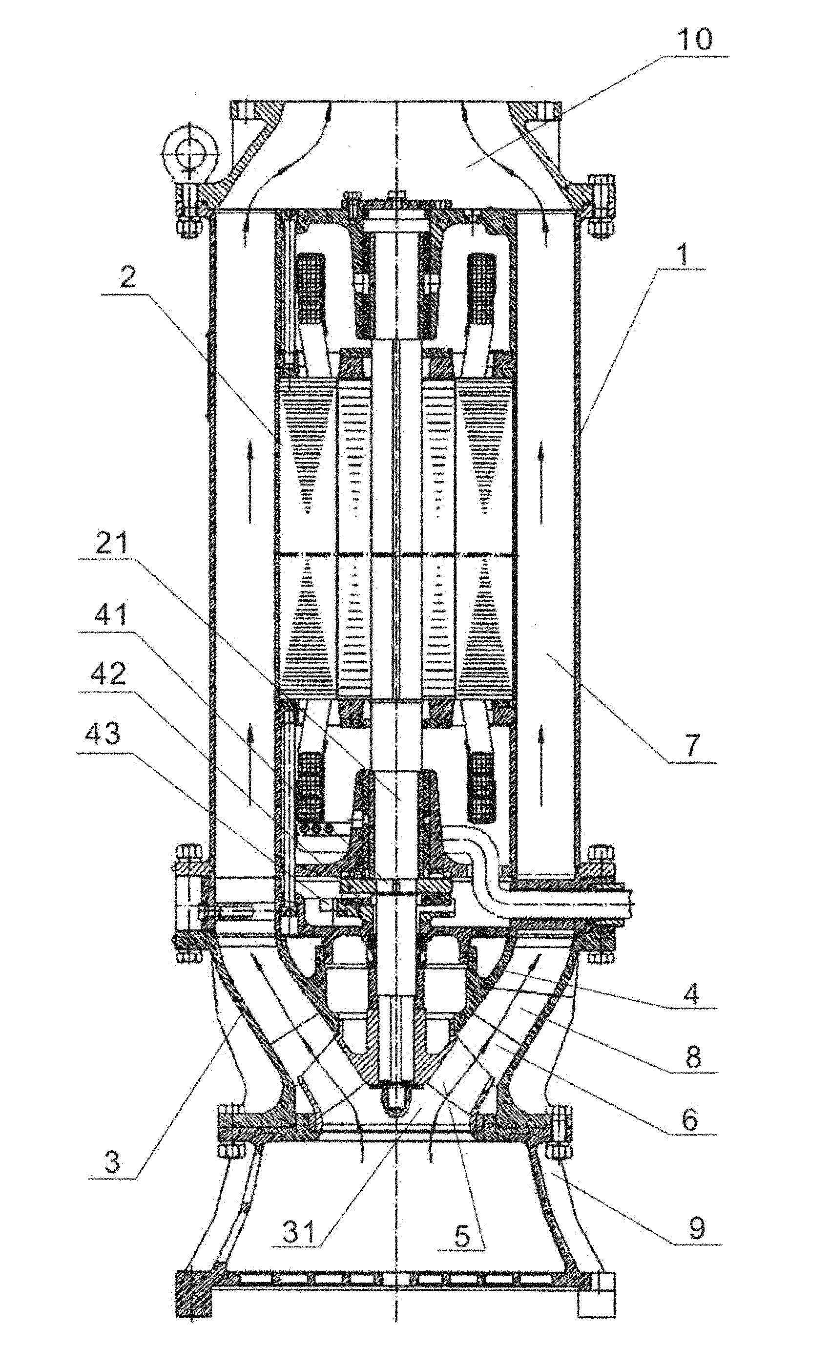
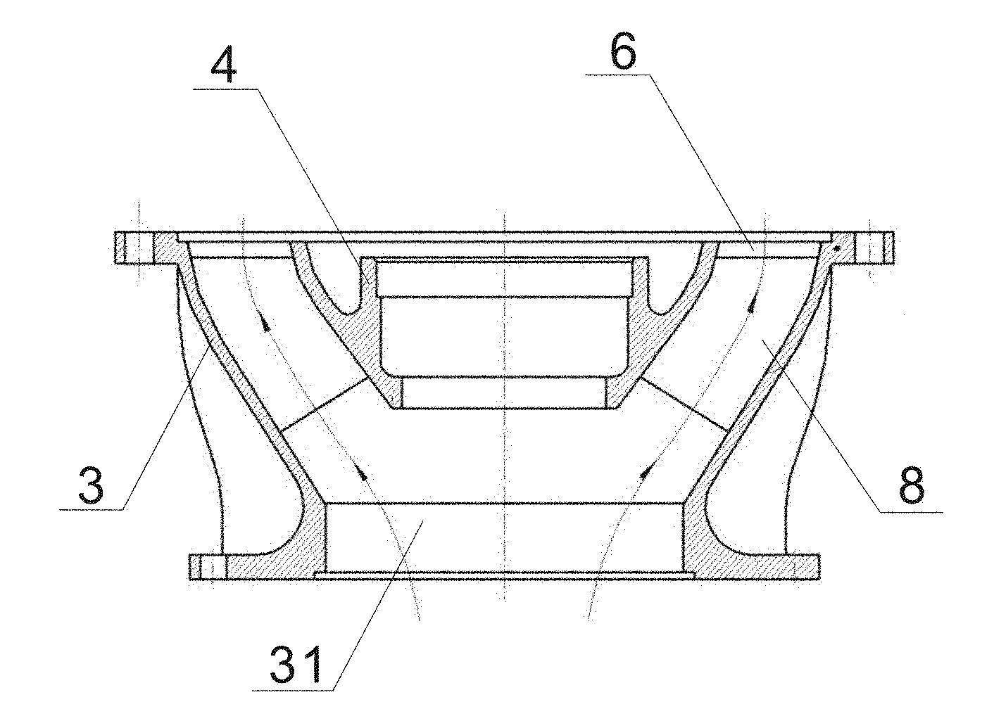
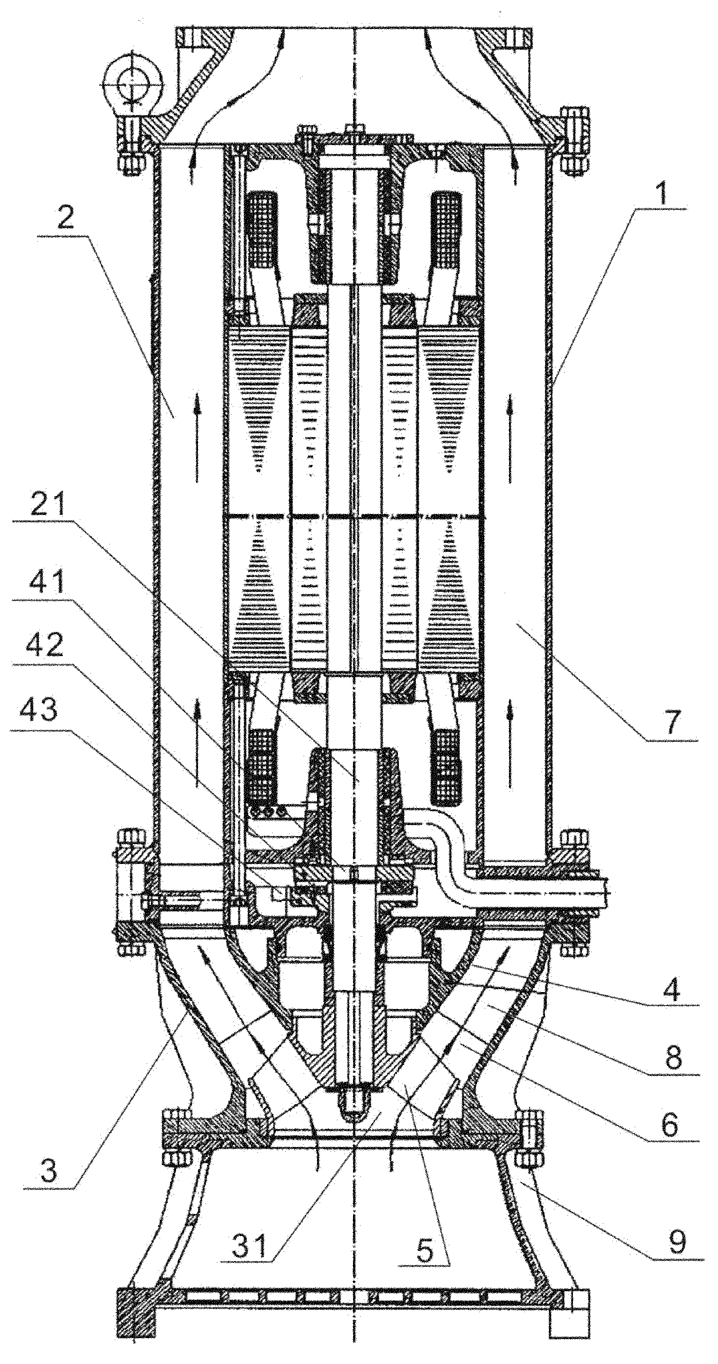
[0018] like figure 1 As shown, a self-cooling guide vane down-suction submersible pump provided by the present invention is mainly composed of a pump casing 1 and a motor 2. In order to ensure the working efficiency of the submersible pump, the motor 2 is preferably a water-filled motor, wherein The motor 2 is set inside the pump body shell 1, and then the water outlet joint 10 is set on the pump body shell 1. In addition, the submersible pump is also provided with a diversion shell 3, and the diversion shell 3 is sealed and fixed under the pump body shell 1. It The bottom of the bottom is provided with a water suction port 31 from which water can enter the submersible pump. In order to ensure that the water flow passes through the diversion shell 3 more smoothly, it is better to arrange several guide vanes 8 in the annular diversion channel 7 inside it. The water su...


PUM


Abstract

The invention discloses a self-cooling guide vane downdraft type submersible pump, and belongs to submersible pumps. The self-cooling guide vane downdraft type submersible pump comprises a pump body casing (1) and an electromotor (2) which is arranged inside the pump body casing (1), wherein a water outlet joint (7) is further arranged on the pump body casing (1). The submersible pump further consists of a guide shell (3) which is hermetically fixed on the lower part of the pump body casing (1), and a water suction port (31) is arranged under the guide shell (3); the output shaft (21) of the electromotor (2) extends into the guide shell (3) and is installed in the interior of the guide shell (3) through a thrust bearing chamber (4), and an impeller (5) is further installed on the output shaft (21). Guide vanes in the guide shell can make water sucked in by the impeller pass through the guide shell more smoothly, and are beneficial to increase of the hydraulic efficiency of the submersible pump, with the lift from 12m to 60m. The self-cooling guide vane downdraft type submersible pump has simple structure, smaller volume and low production cost, and is suitable for the industrialized production.

Description

technical field [0001] The invention relates to a submersible pump, in particular to a self-cooling guide vane down-suction submersible pump. Background technique [0002] At present, the submersible pumps used in the water lifting project of the pumping station choose different power and flow submersible pumps depending on the water flow required in the project. The main working principle is to dive into the water and use the high-speed rotating impeller to transfer the water from the pump The bottom is lifted up, and the raised water is transported to the water use site through the pipeline with its water outlet. However, the submersible pumps in the prior art have structural defects in varying degrees, and the submersible pumps with large flow generally use submersible pumps Mixed-flow pumps, submersible pump impellers with this structure are expensive to manufacture, and their maximum lift is only 12 to 20 meters, but the maximum diameter of its own volume is as high as ...

Claims


Application Information

Patent Timeline
Patent Type & Authority Applications(China)
IPC IPC(8): F04D13/08F04D29/44F04D29/046F04D29/58
Inventor 林玉东谢崇平肖波侯波彭毅信
Owner SICHUAN RUNDE ELECTRICAL TECH
Why Eureka
Try Eureka