
Patsnap Eureka
For R&D, Patsnap Eureka makes reading and utilizing patents & technical documents easy.
Patsnap Eureka AIR
Designed for self-driven R&D workflows. Generate viable solutions, solve complex R&D challenges, empower your innovation with AI.

Patsnap Eureka Materials
Designed for material experts only. Revolutionize your material R&D, from search, analyze, to developing new materials.

TechResearch
Generate reliable direction feasibility study reports for your R&D in just a few steps.

TechSeek
Discover and master advanced knowledge NOW. Basics, ideas, possibilities, all at once.

TechMind
As an expert in R&D Theories, TechMind can generates customized viable solutions instantly.

TechRisk
Analyze your overall solution with one click, know your potential R&D risks in advance.

TechMonitor
Get weekly tech updates, stay abreast of the latest tech innovations and key insights.
Hydraulic automatic gate valve
An automatic, gate valve technology, applied in sliding valves, valve details, valve devices, etc., can solve the problems of high labor intensity, energy consumption, increase costs, etc., and achieve the effect of less investment
- Summary
- Abstract
- Description
- Claims
- Application Information
AI Technical Summary
Problems solved by technology
Method used
Image

Examples
specific Embodiment 1
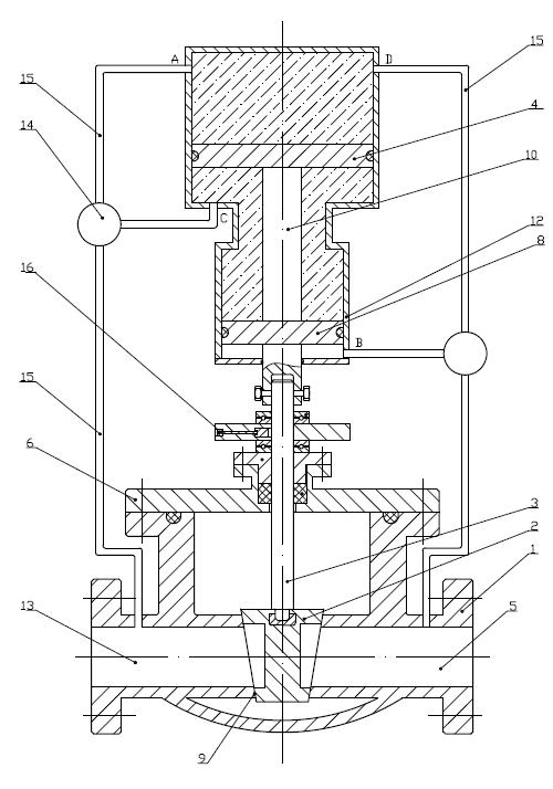
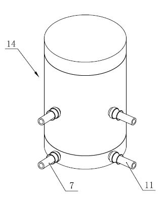
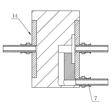
[0016] Specific embodiment 1: as figure 1 As shown in the figure, the liquid automatic gate valve still includes a valve body 1, a valve cover 6, a valve stem 3 and a gate plate 2. The inner cavity of the valve body 1 is provided with a feed channel 13 and a discharge channel 5 on both sides, and the valve cover 6 covers the valve. On the top of the valve body 1, there are valve seats 9 on both sides of the inner cavity of the valve body 1. The lower end of the valve stem 3 passes through the valve cover 6 and enters the inner cavity of the valve body 1. The gate plate 2 is fixed on the lower end of the valve stem 3 and the valve seat 17. Matching, with the upward and downward movement of the valve stem 3, the opening and closing match is formed. In order to realize the use of medium pressure as power, the liquid automatic gate valve is also provided with a valve stem driving oil cylinder 12 and a changeover switch 14 . like figure 2 , 3 As shown, the valve rod driving oil...
specific Embodiment 2
[0019] Specific embodiment 2: as Figure 7 As shown in the figure, the valve rod driving cylinder 12 in the liquid automatic gate valve can also be set upside down, that is, the valve rod driving cylinder 12 is arranged above the valve body 1, the second piston chamber is on the top, the first piston chamber is on the bottom, One end of the piston rod 10 protrudes from the bottom of the first piston cavity and is linked with the upper end of the valve rod 3. The inner cavity of the oil cylinder is divided into three parts by the first piston 4 and the second piston 8: that is, it belongs to the first piston 4 and the second piston 8. The lower part of the first piston chamber of the piston chamber (ie the part at the end of the closing direction); the upper part of the second piston chamber (ie the part at the end of the opening direction) that completely belongs to the second piston chamber and the part between the first piston 4 and the second piston 8 The portion where the ...
PUM
 Abstract
Description
Claims
Application Information
 - R&D Engineer
- R&D Manager
- IP Professional
- Industry Leading Data Capabilities
- Powerful AI technology
- Patent DNA Extraction
Browse by: Latest US Patents, China's latest patents, Technical Efficacy Thesaurus, Application Domain, Technology Topic, Popular Technical Reports.
© 2024 PatSnap. All rights reserved.Legal|Privacy policy|Modern Slavery Act Transparency Statement|Sitemap|About US| Contact US: help@patsnap.com