
Humidifier

A technology of humidifier and main controller, which is applied in the direction of air humidification system, heating method, lighting and heating equipment, etc. It can solve the problems of high production cost, slipping into the water tank by accident, and poor practicability, etc., and achieve practical problems, Solve the overflow problem, the effect of simple structure

Inactive Publication Date: 2011-04-06
MIDEA GRP CO LTD
View PDF4 Cites 10 Cited by
  • Summary
  • Abstract
  • Description
  • Claims
  • Application Information

AI Technical Summary

Problems solved by technology

[0002] As people's requirements for indoor air quality are getting higher and higher, the use of humidifiers has become more and more popular; at present, most of the commercially available humidifiers have a water filling structure, which is a combination of water inlet and water outlet. In the lower part of the water tank, since the water level control is realized by atmospheric pressure, the production of the water tank has high requirements on air tightness. Water chamber, the common problem of humidifiers with this structure is that it is easy to overflow water. At the same time, when adding water, the water tank needs to be removed from the base and inverted before adding water from the water outlet. It is troublesome to do a lot of actions, and because the water tank is heavy after adding water, it is very easy to cause damage to the water tank due to slipping during the moving process; in order to prevent and solve the overflow problem, some manufacturers have made some improvements, as disclosed in Chinese Patent Document No. CN2505751Y Water-filling type ultrasonic humidifier, the ultrasonic humidifier of these structures can add water directly from above when in use, but its structure is more complex, the production cost is relatively high, and the practicability is not strong

Method used


Image

  • Humidifier
  • Humidifier
  • Humidifier

Examples


Embodiment Construction

[0015] The present invention will be further described below in conjunction with the accompanying drawings and embodiments.

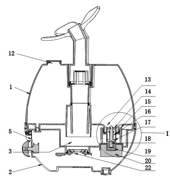
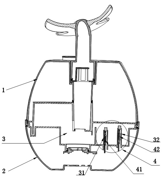
[0016] like figure 1 , 2 As shown, the humidifier of the present invention includes a water tank 1 and a base 2, wherein the water tank 1 is installed above the base 2, the bottom of the water tank 1 and the top of the base 2 form a water storage chamber 3, and the water inlet 12 of the water tank 1 Be arranged at the top, and the water outlet 13 at the bottom of the water tank 1 is provided with a launching mechanism.

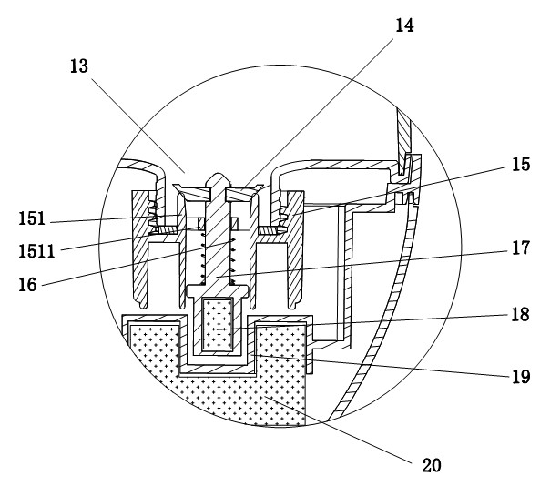
[0017] The water launching mechanism includes a water sealing cover 15, a water sealing rubber 14, a stage clip 16, a push rod 17, a magnet 18 and an electromagnet 20, wherein the main profile cross section of the water sealing cover 15 is H-shaped, and the middle plane of the H shape is H-shaped. A cylindrical sewer channel 151 of substantially equal height is provided, and a guide through hole of the ejector rod 17 is provided at th...


PUM


Abstract

The invention relates to a humidifier which comprises a water tank (1) and a base (2), wherein the water tank (1) is arranged above the base (2), and the bottom of the water tank (1) and the top of the base (2) are enclosed into a water storage chamber (3). The humidifier is characterized in that a water replenishing hole (12) of the water tank (1) is arranged at the top of the water tank (1), and a water outlet (13) at the bottom of the water tank (1) is provided with a water discharging mechanism. Because the structure that the water replenishing hole of the water tank is arranged at the top of the water tank and the water outlet at the bottom of the water tank is provided with the water discharging mechanism is adopted, when the humidifier works, water in the water tank enters the water storage chamber through the water discharging mechanism, when the humidifier stops working, the water discharging mechanism seals the water outlet of the water tank, and water is replenished from the water replenishing hole at the top of the water tank as required, therefore, the humidifier not only is convenient for replenishing water, but also has simple structure; and in addition, a main controller with a multipoint control unit chip is used for automatically measuring and judging water level in the water storage chamber and controlling the water discharging mechanism to execute a water replenishing command, thus the problem of water overflow is completely solved.

Description

technical field [0001] The invention relates to an upper water-filling humidifier, which belongs to the improvement technology of the humidifier. Background technique [0002] As people's requirements for indoor air quality are getting higher and higher, the use of humidifiers has become more and more popular; at present, most of the commercially available humidifiers have a water filling structure, which is a combination of water inlet and water outlet. In the lower part of the water tank, since the water level control is realized by atmospheric pressure, the production of the water tank has high requirements on air tightness. Water chamber, the common problem of humidifiers with this structure is that it is easy to overflow water. At the same time, when adding water, the water tank needs to be removed from the base and inverted before adding water from the water outlet. It is troublesome to do a lot of actions, and because the water tank is heavy after adding water, it is...

Claims


Application Information

Patent Timeline
IPC IPC(8): F24F6/00F24F11/02G01F23/30
Inventor 贾维礼徐杰艾耀平杜孙建莫增甲王朝阳黄平飞
Owner MIDEA GRP CO LTD
Learn More