High-power permanent-magnet motor rotor, installation method of rotor and method for magnetizing rotor permanent magnet

A permanent magnet motor, high-power technology, used in the manufacture of stator/rotor bodies, magnetic circuit rotating parts, wind power generation, etc., can solve the problems of easy generation of magnetic leakage flux, difficult installation of permanent magnets, and inconvenient rotor assembly. Achieve the effect of reducing harmonic content, improving utilization, and simplifying production

Active Publication Date: 2011-04-06
东元总合科技(杭州)有限公司
View PDF7 Cites 59 Cited by
  • Summary
  • Abstract
  • Description
  • Claims
  • Application Information

AI Technical Summary

Benefits of technology

This patented technical effect described in this patents relates to an improved type of electric machine called High Power Permanent Magnet (HPM) motors due to their unique construction feature. These machines have several advantages over traditional designs: they reduce size while still being able to generate more powerful torque compared to older models or even better performance than previous versions. They may include various types of components such as bearings, bushings, coils, etc., allowing them to fit together easily within existing spaces inside the housing. Additionally, these systems allow for easy maintenance and replacement of individual parts, resulting in lower costs associated therewith. Overall, HPM's superiority results in enhanced energy usage capabilities and increased reliability.

Problems solved by technology

This patented technical problem addressed in this patents relates to improving the performance and reliability of rare earth magnetic materials (REM) in various fields like wind turbines or machinery driven through variable speeds without losing their effectiveness over longer periods of use. Current methods involve expensive equipment and complicated processes involving multiple steps during installation process.

Method used


Image

  • High-power permanent-magnet motor rotor, installation method of rotor and method for magnetizing rotor permanent magnet
  • High-power permanent-magnet motor rotor, installation method of rotor and method for magnetizing rotor permanent magnet
  • High-power permanent-magnet motor rotor, installation method of rotor and method for magnetizing rotor permanent magnet

Examples


Embodiment Construction

[0034] In order to make the technical means, creative features, goals and effects achieved by the present invention easy to understand, the present invention will be further described below in conjunction with specific illustrations.

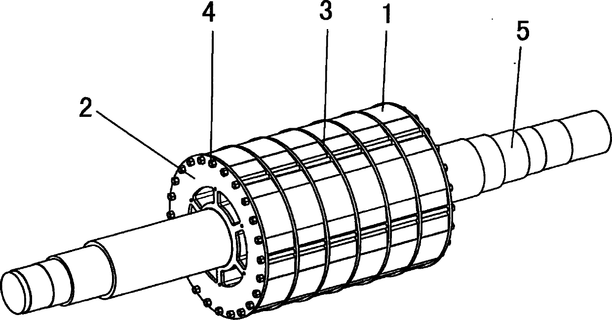
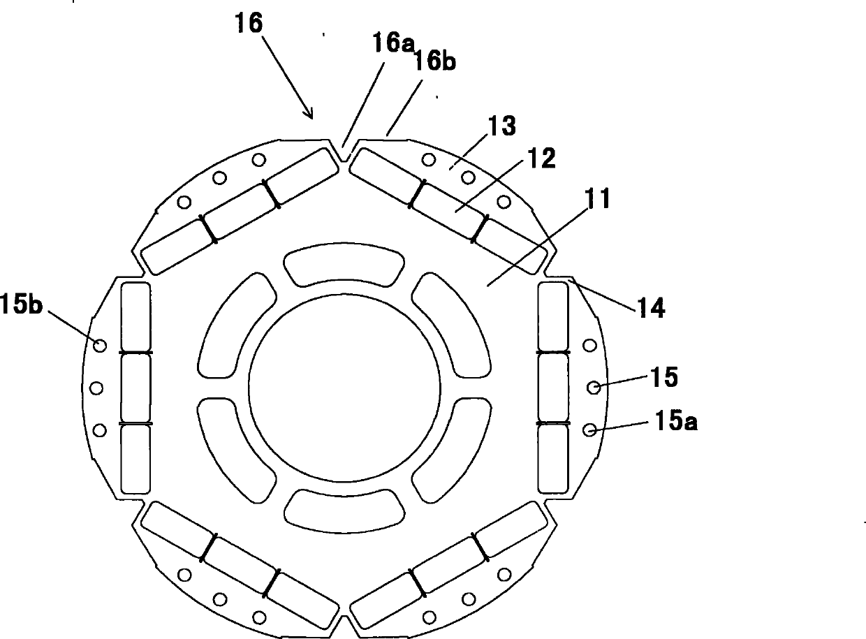
[0035] The gist of the present invention is to provide a high-power permanent magnet motor rotor, especially a rotor used on a high-power permanent magnet synchronous generator, as well as an assembly method of the rotor and a magnetization method of the rotor permanent magnet, so as to solve the problem of For embedded high-power permanent magnet synchronous generators, the permanent magnet magnetic field between adjacent two poles of the rotor is easy to be directly connected, which will cause magnetic flux leakage, resulting in low utilization of permanent magnet materials; during the rotation of the rotor, the rotor permanent magnet and The rotor pole shoes are subjected to centrifugal force in the relative direction of rotation, and the cent...


PUM


Abstract

The invention provides a high-power permanent-magnet motor rotor especially suitable for high-power permanent-magnet synchronous windmill generators, an installation method of the rotor and a method for magnetizing a permanent magnet. By adopting a permanent magnet embedded structure, the rotor is divided into a plurality of axial rotor units, and the iron core between every adjacent two pole permanent magnets of each rotor unit is provided with a rotor-axial magnetic isolation groove which is fixed by a partition between an end plate and the rotor unit. The rotor not only avoids magnetic leakage and enhances the intensity, but also simplifies the manufacture and assembly of the rotor as well as the magnetizing procedure of the permanent magnet, thereby enhancing the production efficiency.

Description


Claims


Application Information

Patent Timeline
Owner 东元总合科技(杭州)有限公司
Why Eureka
Try Eureka