Self-oscillation type SCR (Semiconductor Control Rectifier) drive interlock circuit

A technology of self-oscillating and interlocking circuits, applied in the field of electric power, can solve the problems of increasing circuit complexity and cost, achieve the effects of reducing cost and complexity, simple and reliable control, and reducing control logic

Active Publication Date: 2012-10-31
易事特集团(萍乡)有限公司
View PDF0 Cites 0 Cited by
  • Summary
  • Abstract
  • Description
  • Claims
  • Application Information

AI Technical Summary

Problems solved by technology

[0002] In the UPS control system, the bypass SCR control signal and the inverter SCR control signal are mostly independent and interlocked two-way control signals. The control signal circuit and the drive power circuit are two separate parts, which are not connected to each other. The power supply used for SCR switching control is generally separated from the control signal, and 384X series or 352X series are mostly used to generate driving power independently, which increases the complexity and cost of the circuit

Method used


Image

  • Self-oscillation type SCR (Semiconductor Control Rectifier) drive interlock circuit

Examples


Embodiment Construction

[0012] The present invention will be further described in conjunction with the following examples.

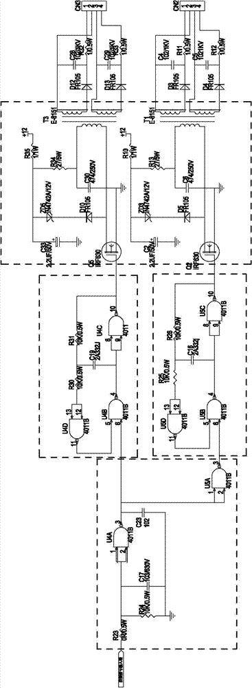
[0013] An embodiment of the self-excited oscillation type SCR drive interlock circuit of the present invention is as figure 1 As shown, it includes a control signal loop, a self-excited oscillation loop 1 and a self-excited oscillation loop 2, and an isolated drive circuit; the control signal loop includes resistors R23, R24, C17, C23 and 4011 elements U4A and U5A; The self-excited oscillation loop 1 includes 4011 components U4D, U4B, U4C, resistors R30, R31, and capacitor C19; the self-excited oscillation loop 2 includes U5D, U5B, U5C, R25, R26, and C16;

[0014] One end of R23 is connected to the control signal input end, the other end of R23 is connected to one end of R24, one end of C17 and the input end of U4A, the other end of R24 and the other end of C17 are grounded; the output end of U4A is connected to one end of C23 and the input end of U5A And one input terminal of...


PUM


Abstract

The invention relates to a self-oscillation type SCR (Semiconductor Control Rectifier) drive interlock circuit, comprising a control signal loop, a self-oscillation loop (1), a self-oscillation loop (2) and an isolating drive circuit. The control signal loop comprises resistors (R23 and R24), a capacitor (C17) and 4011 elements (U4A and U5A), the self-oscillation loop (1) comprises 4011 elements (U4D, U4B and U4C), resistors (R30 and R31) and a capacitor (C19), and the self-oscillation loop (2) comprises 4011 elements (U5D, U5B and U5C), resistors (R25 and R26) and a capacitor (C16). The invention realizes the functions of generating, interlocking and switching two paths of SCR driving power supplies by utilizing a path of control signal and utilizing a self-oscillation circuit (1) and a self-oscillation circuit (2) formed by the 4011 elements and switching a bypass power supply and an inverter power supply of a UPS (Uninterrupted Power Supply) by only needing a path of control signalwithout an additional driving power supply circuit, thereby lowering the cost and the complication degree of the circuit, lessening the control logic and having simple and reliable control.

Description

technical field [0001] The invention relates to the field of electric power technology, in particular to a self-excited oscillation SCR driving interlock circuit. Background technique [0002] In the UPS control system, the bypass SCR control signal and the inverter SCR control signal are mostly independent and interlocked two-way control signals. The control signal circuit and the drive power circuit are two separate parts, which are not connected to each other. The power supply used for SCR switching control is generally separated from the control signal, and 384X series or 352X series are mostly used to generate driving power independently, which increases the complexity and cost of the circuit. Contents of the invention [0003] The object of the present invention is to provide a self-excited oscillation SCR drive interlock circuit to avoid the disadvantages of the prior art. [0004] The object of the present invention is achieved through the following technical meas...

Claims


Application Information

Patent Timeline
Patent Type & Authority Patents(China)
IPC IPC(8): H02M1/06
Inventor 戴宝锋
Owner 易事特集团(萍乡)有限公司
Why Eureka
Try Eureka