

Immersion nozzle for continuous casting
An immersion, nozzle technology, applied in casting equipment, casting melt containers, manufacturing tools, etc., can solve the problems of oxidizing molten metal, metal penetration of joints, quality deterioration, etc., and achieve the effect of improving rigidity
- Summary
- Abstract
- Description
- Claims
- Application Information
AI Technical Summary
Problems solved by technology
Method used
Image

Examples
Embodiment
[0040] Hereinafter, preferred embodiments of the submerged nozzle for continuous casting according to the present invention will be described with reference to the accompanying drawings.
[0041] In addition, the same or equivalent parts as those in the conventional embodiments are described using the same symbols.
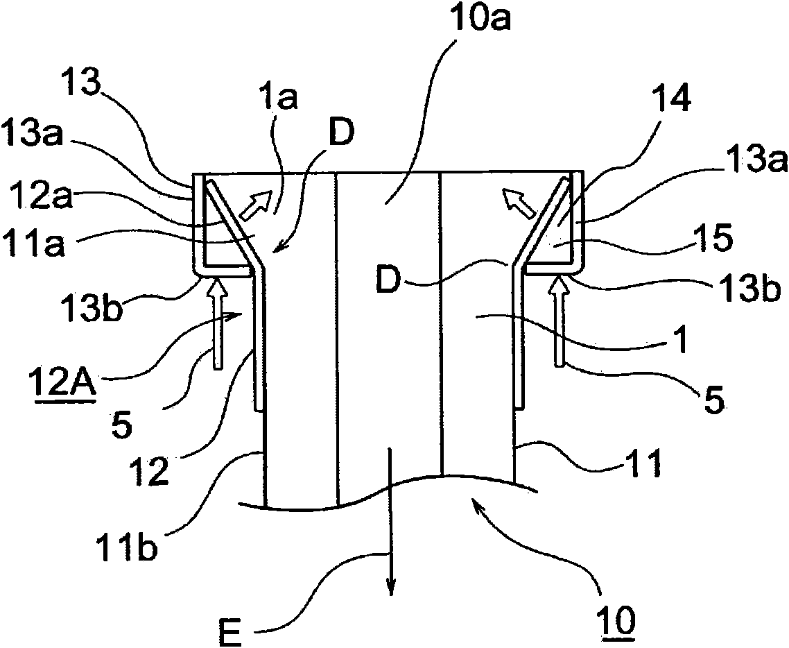
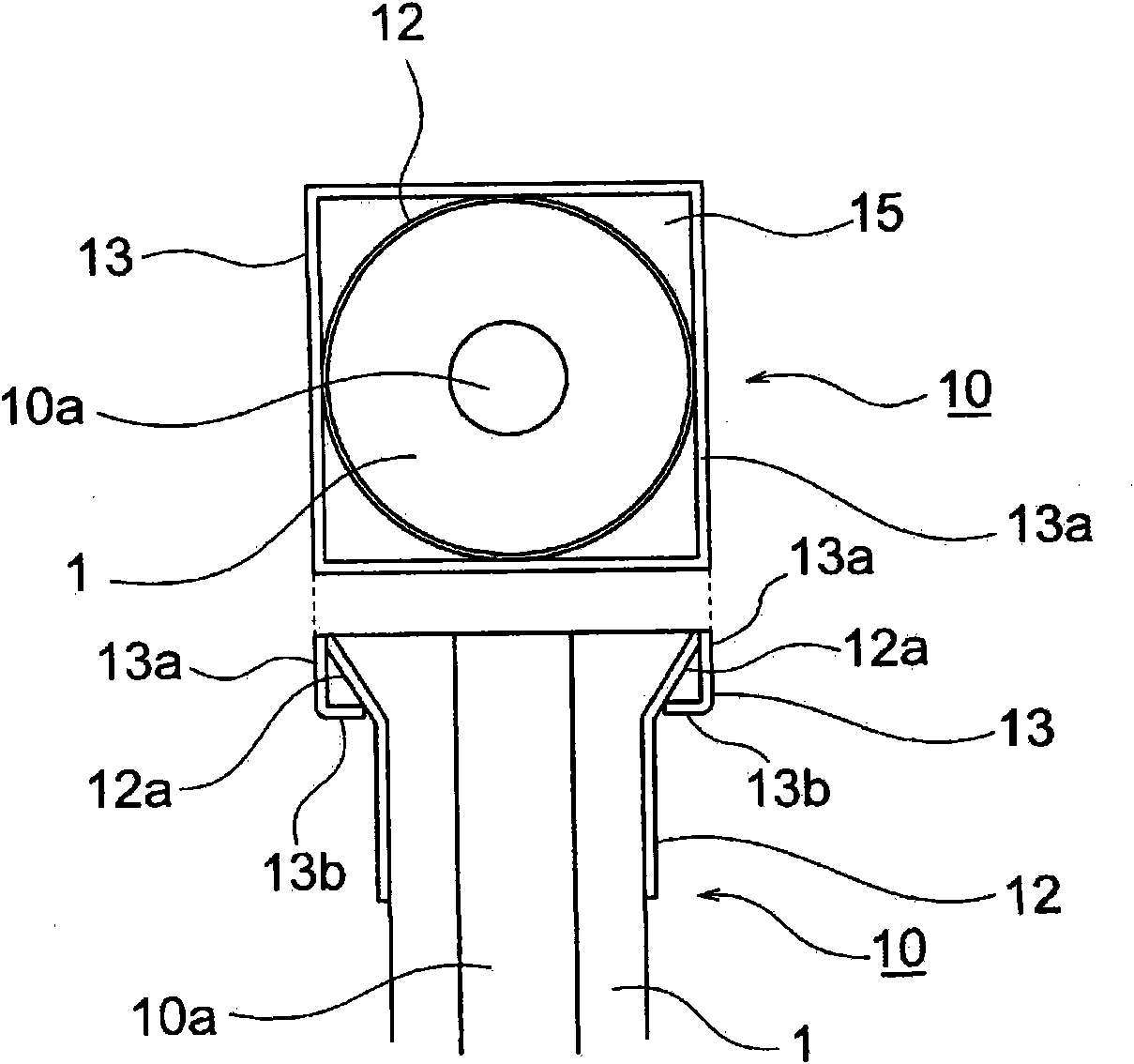
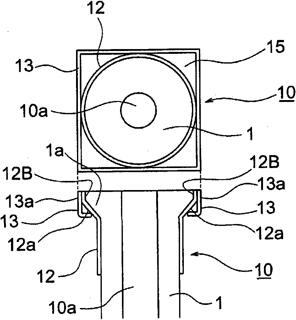
[0042] figure 1 To illustrate the figure of the first embodiment of the present invention, in figure 1 The part denoted by the symbol 1 is a long cylindrical refractory, which is used to constitute the submerged nozzle 10 for continuous casting used in the slide valve, and the axial center position of the cylindrical refractory 1 is penetrated and formed There is molten steel injection hole 10a.
[0043] The outer surface 11 of the cylindrical refractory 1 is composed of an upper tapered portion 11a and a straight line portion 11b formed below the tapered portion 11a.
[0044] The metal member 12A provided on a part or the whole of the outer surface 11 is compo...
PUM
 Abstract
Description
Claims
Application Information