
Machine tool having an electric drive motor

A technology for electric drive motors and machine tools, which is applied in the direction of manufacturing tools, portable motorized devices, metal processing equipment, etc., can solve the problems of reducing heat discharge, function failure, and pollution of drive motor machine tool parts, and achieves improved flow guidance and less The effect of losing power

Active Publication Date: 2011-04-06
ROBERT BOSCH GMBH
View PDF1 Cites 1 Cited by
  • Summary
  • Abstract
  • Description
  • Claims
  • Application Information

AI Technical Summary

Problems solved by technology

Since abrasive dirt particles occur during the machining of workpieces in hand-held power tools, which are introduced into the interior of the housing via the cooling air flow, the drive motor and other components in the housing are present. Risk of contamination of machine tool components
The abrasive particles can deposit in the housing and cause, for example, wear on the ends of the pole shoe windings of the electric drive motor, which can lead to short circuits and at the same time lead to functional failures
Furthermore, the dirt particles increase friction and impair the cooling efficiency of the cooling air flow, thereby reducing heat dissipation

Method used


Image

  • Machine tool having an electric drive motor
  • Machine tool having an electric drive motor
  • Machine tool having an electric drive motor

Examples


Embodiment Construction

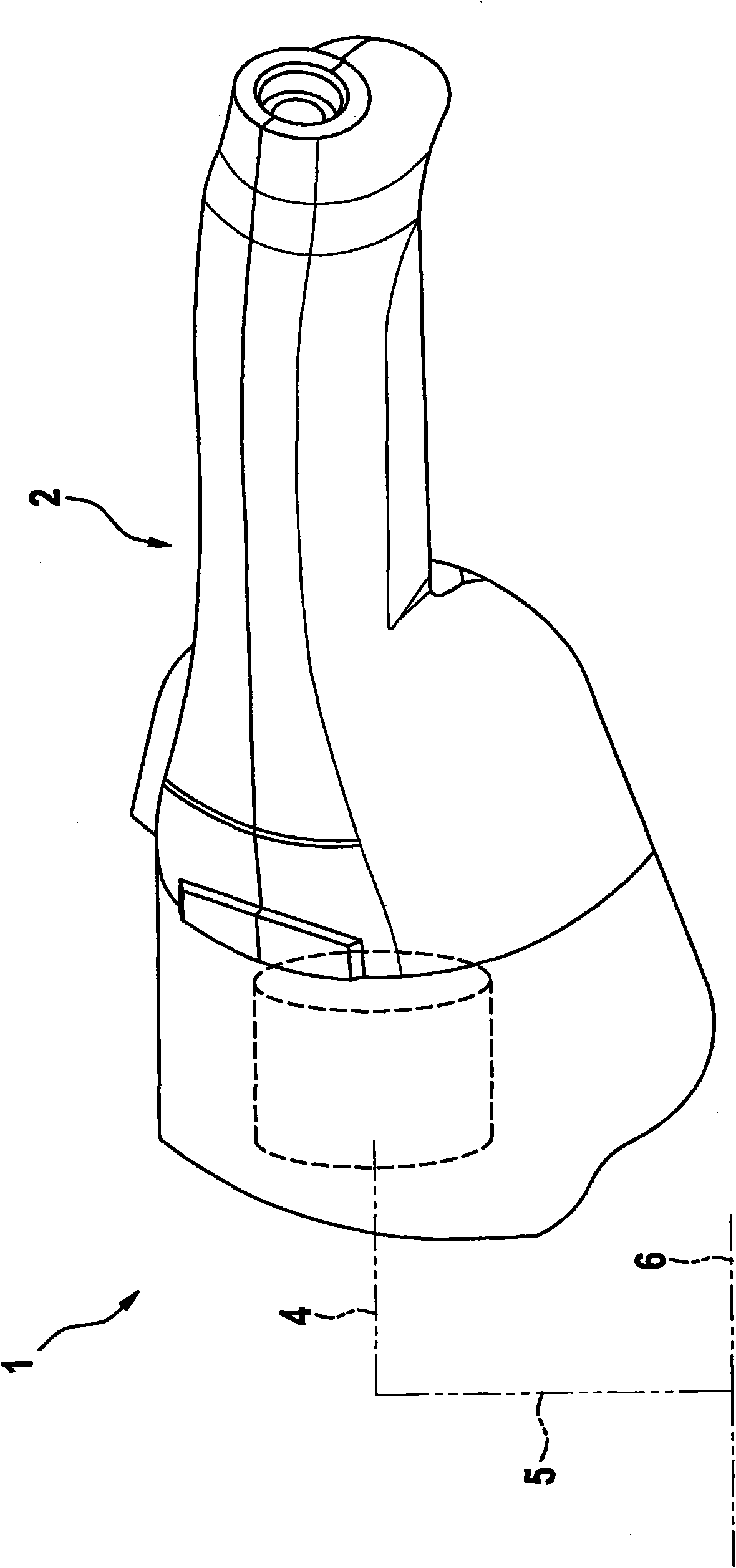
[0020] figure 1 The hand-held power tool 1 shown in a general manner has an electric drive motor 3 in a housing 2, which is designed as an AC motor, preferably as a series motor, wherein a DC motor is also conceivable if necessary . The rotor shaft or armature shaft 4 of the drive motor is rotationally coupled to and drives a tool shaft 5 mounted rotatably in the housing, on which a tool 6 for machining a workpiece is fastened.

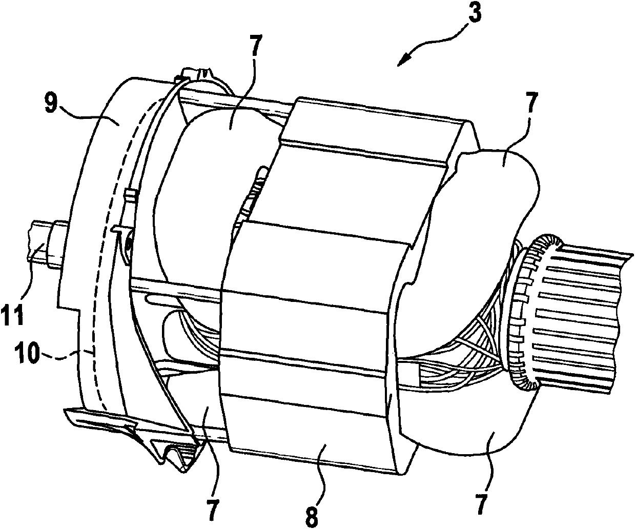
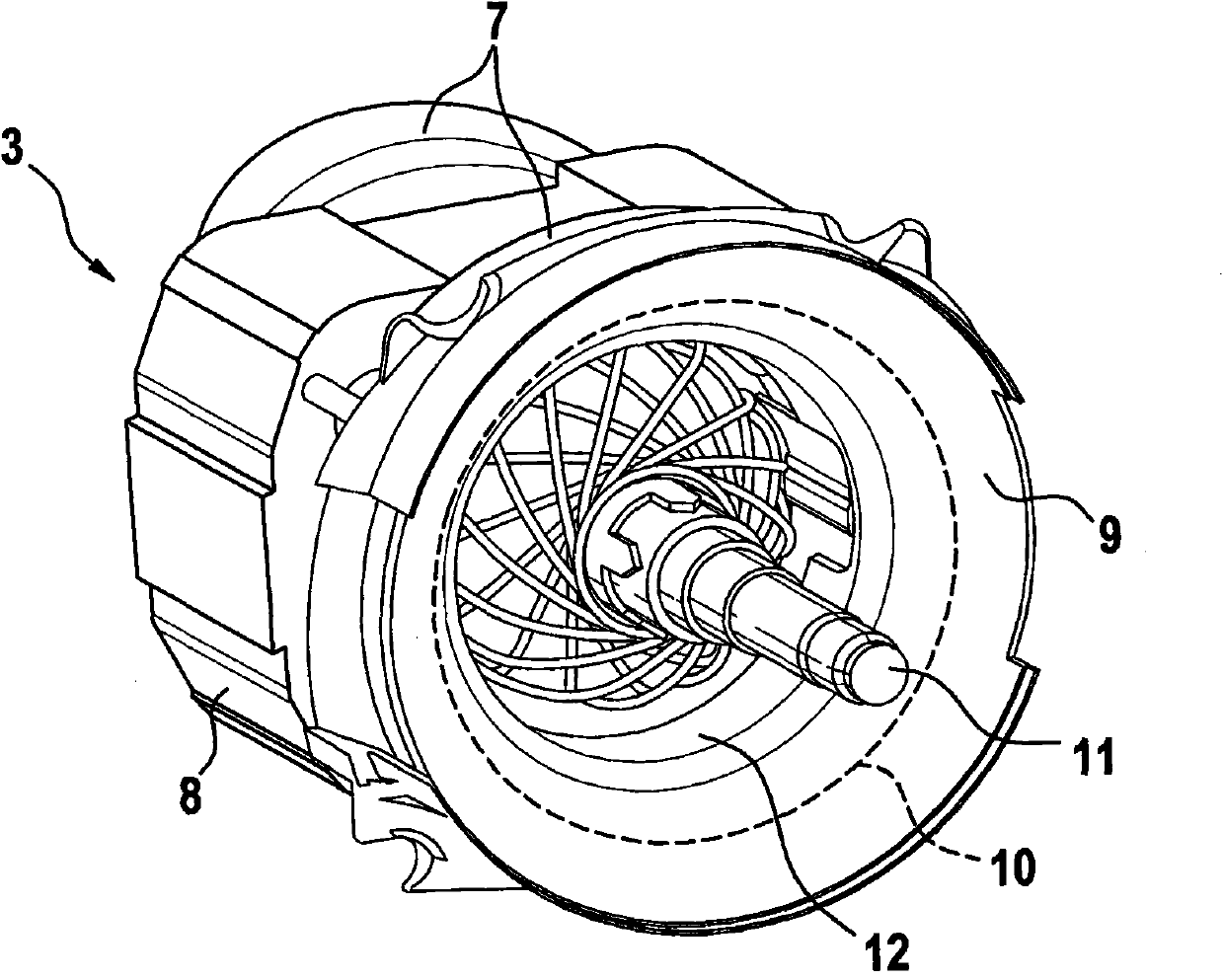
[0021] From figure 2 and 3 It can be seen from the figure that the electric drive motor 3 has a pole shoe 7 which is designed in particular as a winding end and forms part of the stator of the drive motor. Furthermore, there is a grounding part 8 which surrounds the pole piece 7 in a ring, which can optionally also have permanent magnets.

[0022] On one end side of the electric drive motor 3 is arranged coaxially to the rotor shaft or armature shaft 11 of the drive motor an air guide ring 9 in which a fan impeller, shown only schematically, can ...


PUM


Abstract

A machine tool, in particular a powered hand tool, has an electric drive motor to which pole shoes are assigned in order to conduct a magnetic field. Furthermore, a fan wheel is provided in order to produce a stream of cooling air. In the housing, an air-guiding element forms a portion of the flow path for the stream of cooling air, wherein the air-guiding element at least partially covers the pole shoes.

Description

technical field [0001] The invention relates to a machine tool, in particular a hand-held machine tool with an electric drive motor as stated in the preamble of claim 1 . Background technique [0002] Hand-held power tools with an electric drive motor, in particular angle grinders, have in the housing a fan wheel for cooling the motor, which is driven by the motor and generates a cooling air flow which is guided through the hand-held machine. machine tool housing. Since abrasive dirt particles occur during the machining of workpieces in hand-held power tools, which are introduced into the interior of the housing via the cooling air flow, the drive motor and other components in the housing are present. Risk of contamination of machine tool parts. The abrasive particles can deposit in the housing and cause, for example, wear on the ends of the pole shoe windings of the electric drive motor, which can lead to short circuits and at the same time lead to functional failures. I...

Claims


Application Information

Patent Timeline
Patent Type & Authority Applications(China)
IPC IPC(8): B24B23/02B25F5/00
CPCB24B23/028B25F5/008
Inventor R·福尔摩M·舒勒
Owner ROBERT BOSCH GMBH
Learn More