

Train braking apparatus and train braking method
A braking device, a technology for trains, applied in the direction of brakes, operating mechanisms of railway vehicle brakes, braking components, etc., can solve the problems of deceleration fluctuations, inability to obtain braking force, friction coefficient differences, etc., and achieve the effect of deceleration stability.
- Summary
- Abstract
- Description
- Claims
- Application Information
AI Technical Summary
Problems solved by technology
Method used
Image

Examples
Embodiment approach 1
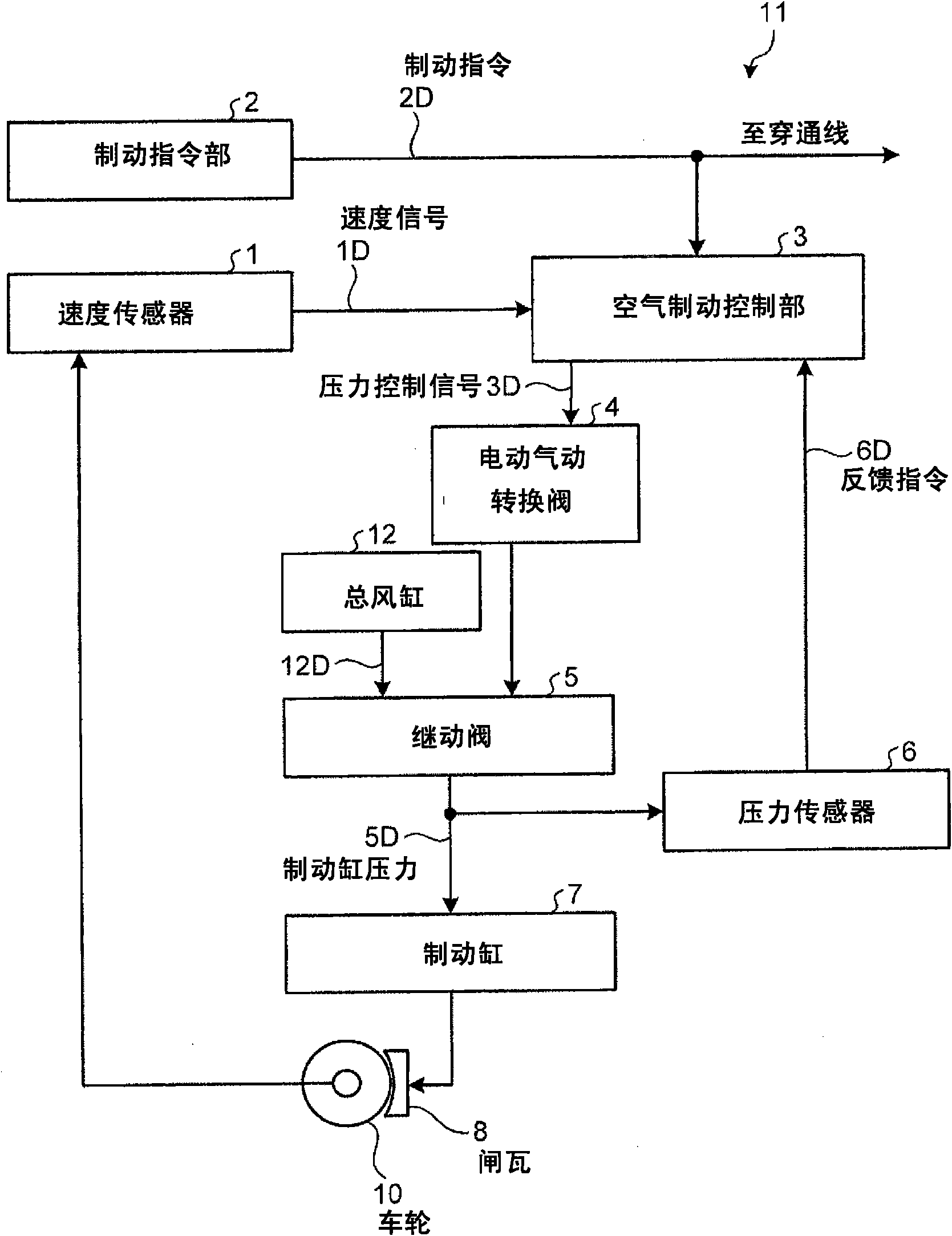
[0045] figure 1 It is a figure which shows an example of the structure of the train brake apparatus concerning Embodiment 1. figure 1 The shown train brake device 11 adopts the following structure: as the main components, it has a speed sensor 1, a brake instruction unit 2, an air brake control unit 3, an electropneumatic switching valve 4, a relay valve 5, a pressure sensor 6, Brake cylinder 7, brake shoe 8, wheel 10, and total air cylinder 12.
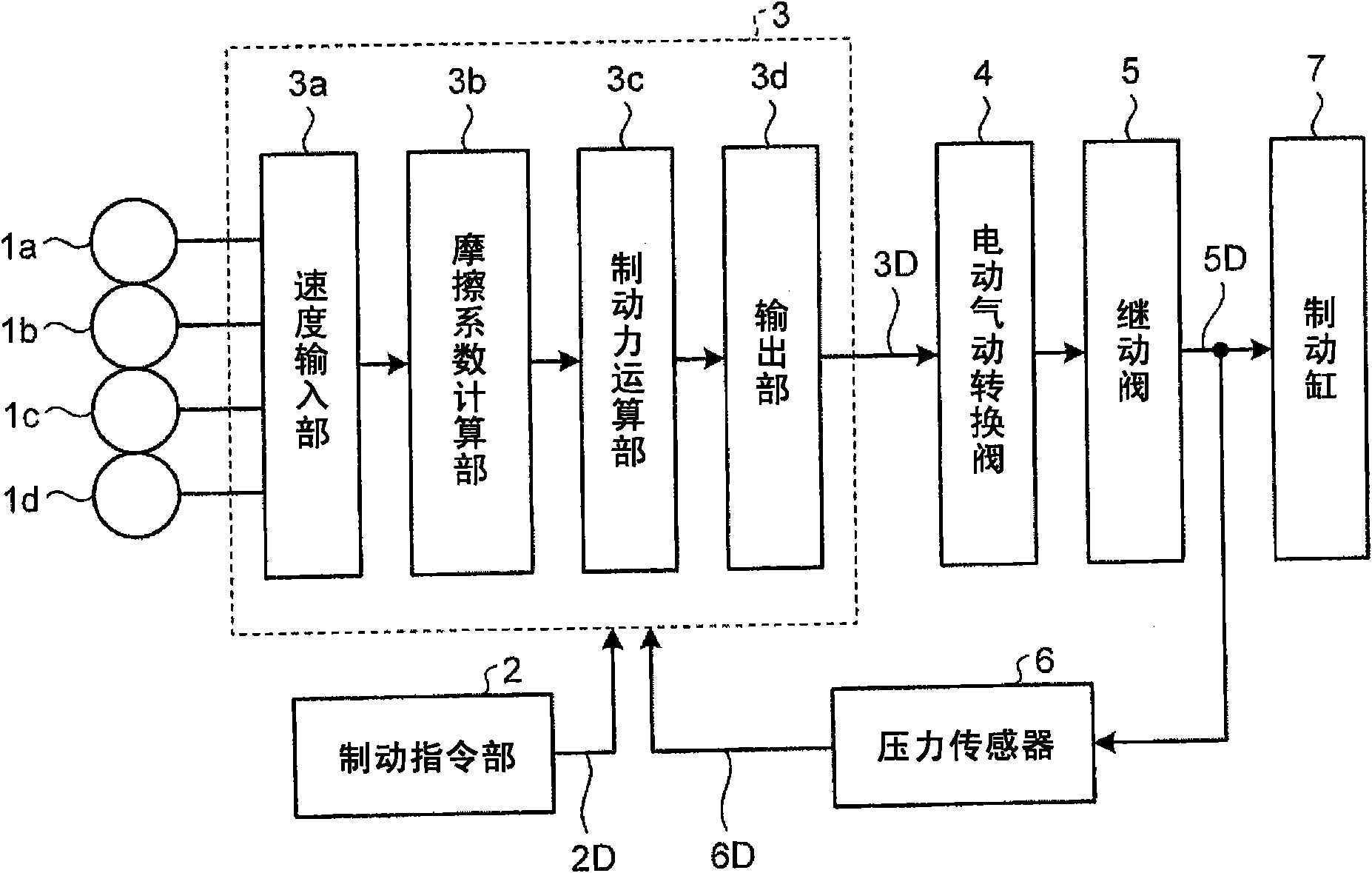
[0046] The speed sensor 1 is installed on the front and rear bogies of each vehicle (4 in total), and can acquire the speed signal 1D of each wheel 10 . The speed input unit 2 can acquire a speed signal 1D from the speed sensor 1a to the speed sensor 1d of each vehicle.
[0047] The brake command unit 2 can output a brake command 2D for obtaining a predetermined deceleration. The air brake control unit 3 receives the brake command 2D sent from the brake command unit 2, and a load compensation signal sent from a load compensation d...
Embodiment approach 2
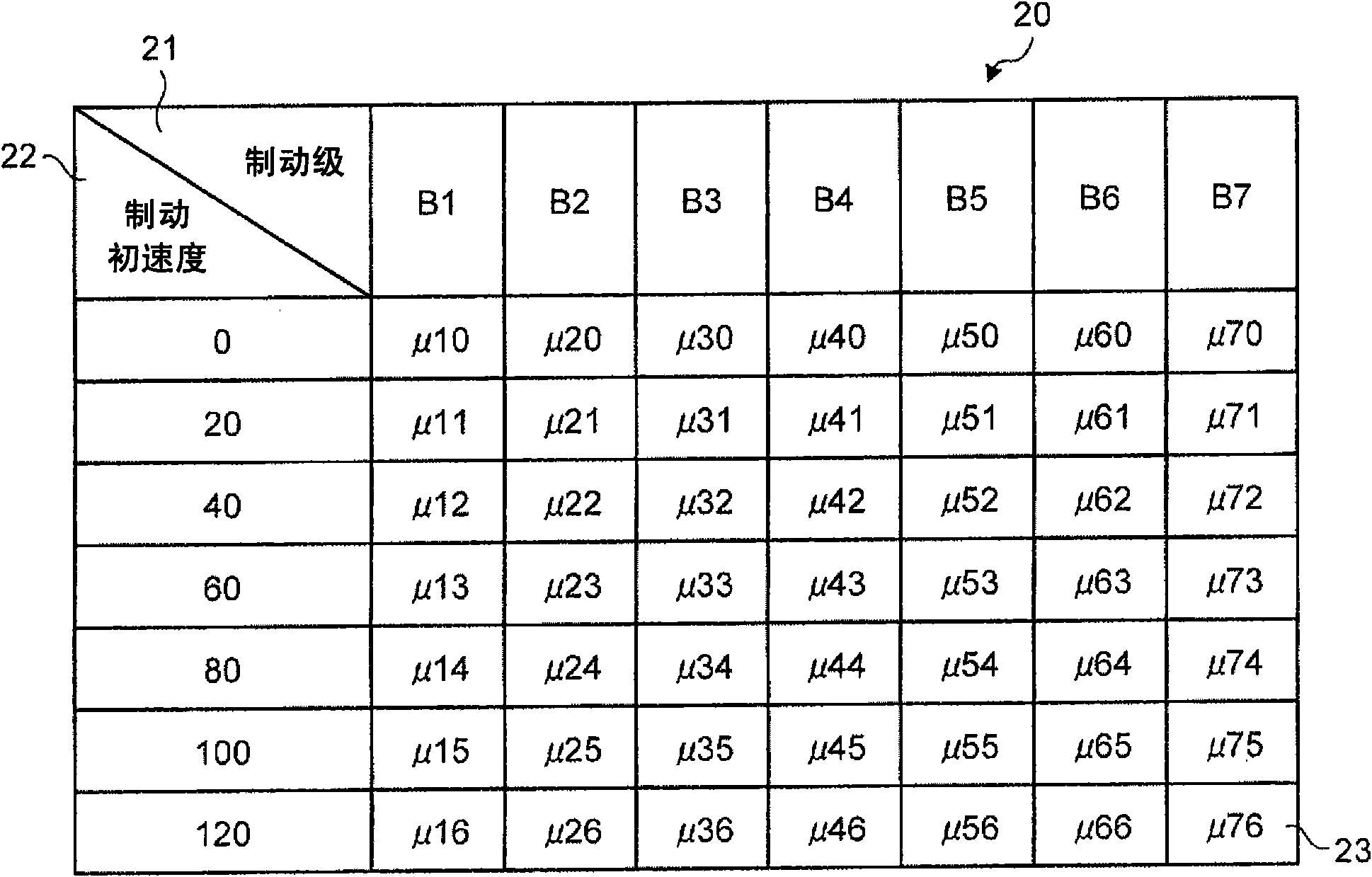
[0069] The train braking device 11 according to the second embodiment has a structure that can reduce the difference in the friction coefficient 23 due to the difference in the use time of the brake shoe 8, and can obtain stable deceleration. In addition, the structure of the train braking device 11 is the same as that in Embodiment 1. figure 1 and figure 2 The structure shown is the same.
[0070] Here, the braking force can be obtained from the product of the brake cylinder pressure 5D and the friction coefficient 23 as described above. Here, the replacement cycle of the brake shoe 8 varies depending on the number of passengers and the use environment. Generally, the longer the use time, the smaller the value of the friction coefficient 23 of the brake shoe 8 . That is, the value of the friction coefficient 23 of the brake shoe 8 whose replacement time is early and whose traveling distance (use time) is long shows a lower value than that of the brake shoe 8 whose replacem...
PUM
 Abstract
Description
Claims
Application Information