Soybean milk machine
A technology for a soymilk maker and milk storage, which is applied in the field of disturbing fluid for household soymilk maker, can solve the problems of inconvenient cleaning and insufficient crushing of beans, and achieve the effects of easy disassembly, shortening pulping time and reducing noise.
- Summary
- Abstract
- Description
- Claims
- Application Information
AI Technical Summary
Problems solved by technology
Method used
Image
Examples
Embodiment 1
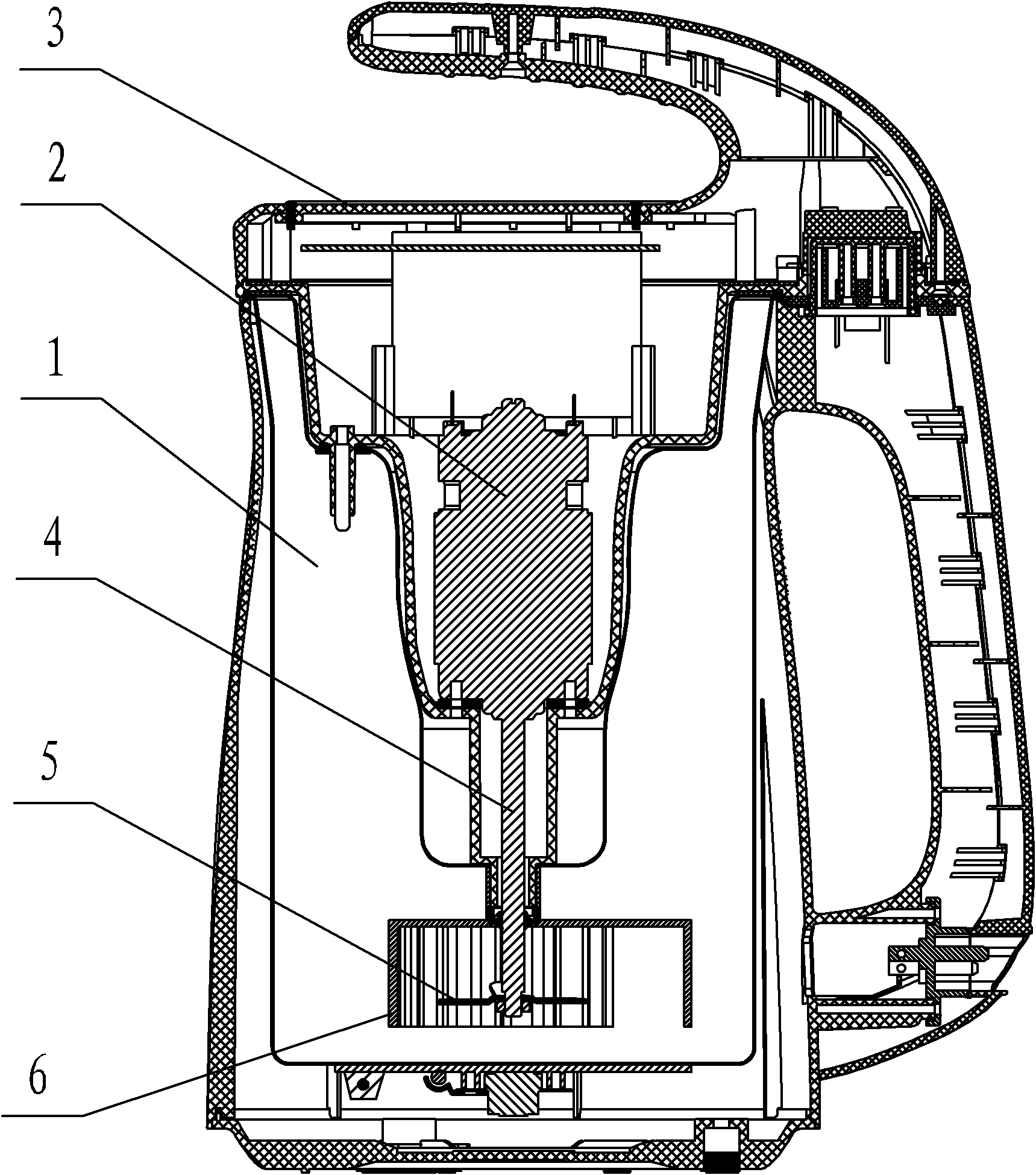
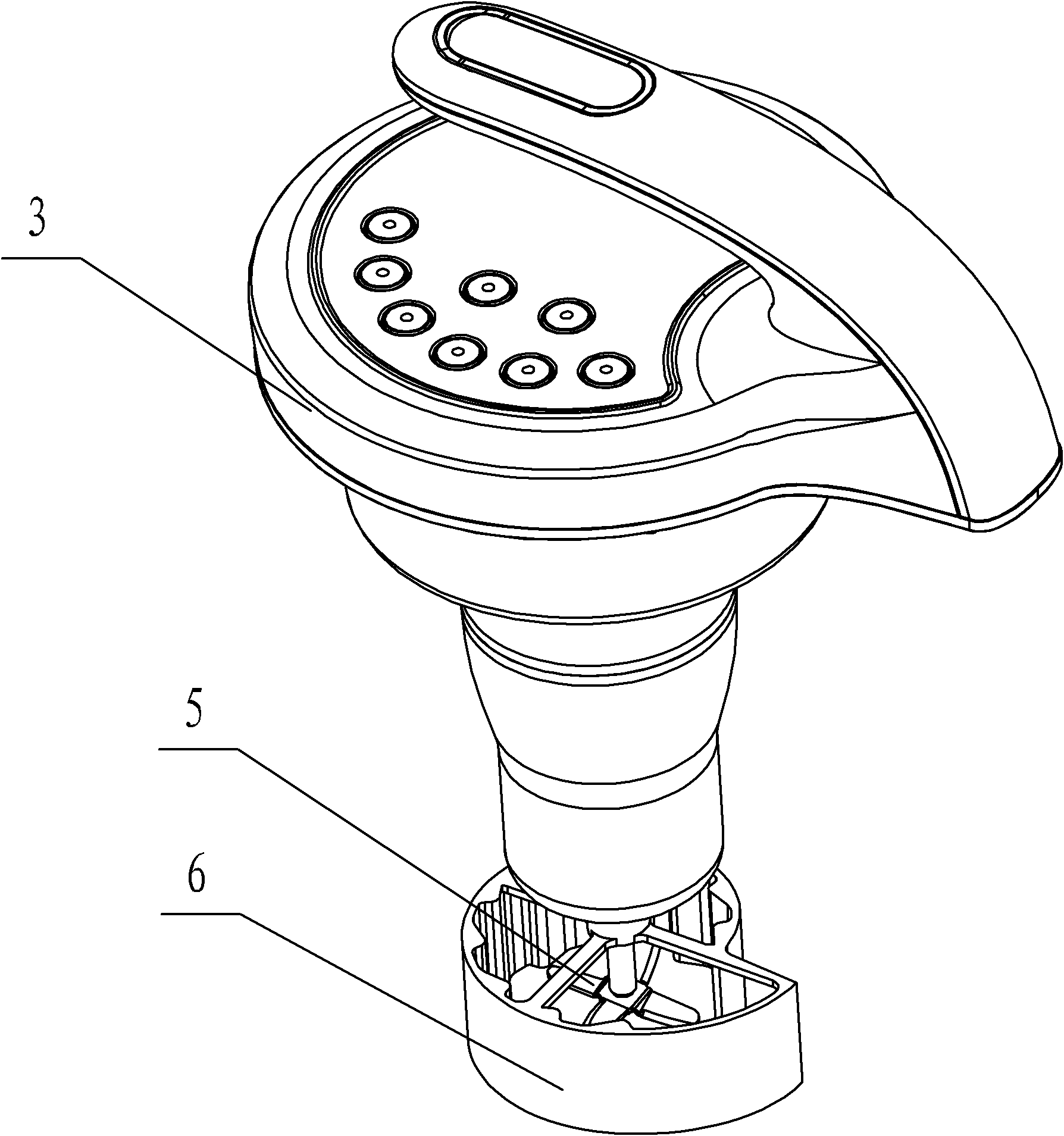
[0052] from figure 1 , figure 2 , Figure 6-9 , Figure 17 It can be seen that a soybean milk machine of the present invention includes a milk container 1 with an open top, a motor 2 as a power source, the motor 2 is accommodated in a motor housing 3, and an output shaft 4 extends through the motor housing 3 Into the slurry container 1, the end of the output shaft 4 of the motor 2 is connected with a crushing knife 5, and also includes a turbulent body 6 located around the crushing knife 5, and the turbulent body 6 extends along a semi-closed curve as a whole. The turbulent body 6 is located on the track extending from the inner wall of the pulp container 1 to the output shaft 4 of the motor 2, and the extension direction is the same as the rotation direction of the crushing knife 5, so that the beans gather toward the center with the water flow. Compared with the prior art, the soymilk maker of the technical solution of this embodiment improves the pulping effect because ...
Embodiment 2
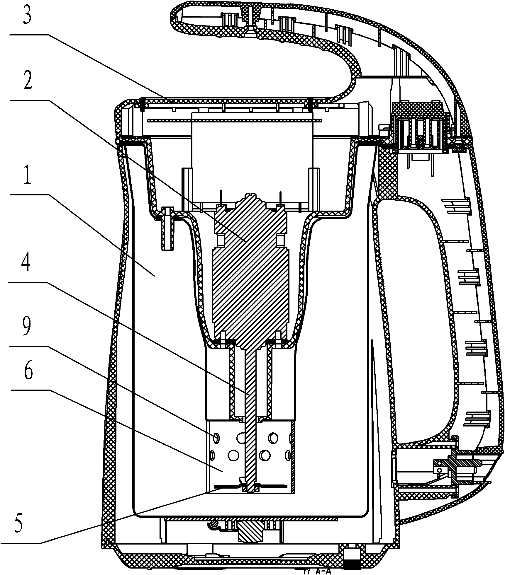
[0062] from image 3 , Figure 4 , Figure 12-14 It can be seen that the difference between this embodiment and the first embodiment is that the turbulent body is as follows Figure 14 semicircle as shown, and as Figure 4 , Figure 12 The arc shown is centered on the output shaft of the motor. The purpose of the opening is to let the material flow in and out through a unified place, forming a more regular liquid flow direction, which is conducive to the overall crushing effect of the material. like Figure 4 , Figure 12 As shown, the arc selects a circular ring with a value of 3 / 4. like Figure 14 As shown, the arc selects a circular ring with a value of 1 / 2.
[0063] like Figure 4 As shown, the turbulent body is provided with a guide hole 9 . The guide hole 9 is opened on the upper part of the turbulent body 4 . The diversion hole 9 can divert the liquid and help to speed up the flow of the liquid, thereby speeding up the cutting and crushing of the material. ...
Embodiment 3
[0066] from Figure 5 , Figure 10-11 , Figure 15-16 It can be seen that the difference from the first embodiment is that the extending track of the turbulent body 6 is roughly a helical line 7 .
[0067] The diameter of the inner ring of the helix 7 is φ d1 , the blade outer diameter φ of the crushing knife 5 d Inner ring diameter φ with helix 7 d1 The ratio of α is 0.1<α≦8, preferably the ratio is 3, at this time the eddy current effect formed by the disturbing body 6 is the best. The vertical spacing H of the helix 7 is 5mm<H≤65mm, preferably 15mm, and the liquid flow direction is the best at this time. The transverse spacing L of the helix 7 is 3mm<L≤35mm, preferably 8mm, and the helical liquid flow formed at this time is the best.
PUM
 Abstract
Description
Claims
Application Information
 - R&D
- Intellectual Property
- Life Sciences
- Materials
- Tech Scout
- Unparalleled Data Quality
- Higher Quality Content
- 60% Fewer Hallucinations
Browse by: Latest US Patents, China's latest patents, Technical Efficacy Thesaurus, Application Domain, Technology Topic, Popular Technical Reports.
© 2025 PatSnap. All rights reserved.Legal|Privacy policy|Modern Slavery Act Transparency Statement|Sitemap|About US| Contact US: help@patsnap.com


