Eureka AIR delivers breakthrough ideas for toughest innovation challenges, trusted by R&D personnel around the world.

Forging process for producing mushroom-shaped flange on die forging hammer

A mushroom-shaped, die-forging hammer technology, applied in the field of forging technology, can solve the problems of full flange shaft, increased production cost, and difficult to achieve, and achieves the effect of increasing flow speed, ensuring fullness, and facilitating fullness

Inactive Publication Date: 2011-04-13
广东省韶铸集团有限公司
View PDF6 Cites 5 Cited by
  • Summary
  • Abstract
  • Description
  • Claims
  • Application Information

AI Technical Summary

Problems solved by technology

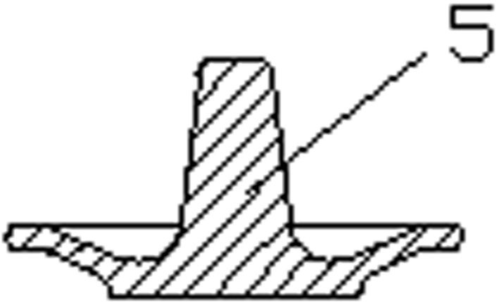
[0002] like figure 1 Shown is a mushroom-shaped flange forging. The flange is shaped like a mushroom, so it is commonly called a mushroom-shaped flange. According to the shape and size requirements of the flange, combined with the previous forging process, it is necessary to It is difficult to ensure that the shaft portion of the flange is full
[0003] For mushroom-shaped flanges, due to the large difference between the diameter of the shaft end (Ф84) (average diameter of the shaft Ф110) and the diameter of the flange (Ф550), it is difficult to meet the material distribution principle of the blank in the process, and it is impossible to ensure that the shaft is completely After calculation and analysis, the forging plan is finally determined: pre-forging and final forging are performed on the die forging hammer twice; if the trial die forging cannot meet the size requirements of the forging, an additional fire will be considered, and the billet will be opened by free forging Prefabricated blanks, and then die forging, but this will increase the fuel consumption and material consumption of a fire, reduce production efficiency, and lead to an increase in production costs

Method used


Image

  • Forging process for producing mushroom-shaped flange on die forging hammer
  • Forging process for producing mushroom-shaped flange on die forging hammer
  • Forging process for producing mushroom-shaped flange on die forging hammer

Examples


Embodiment Construction

[0014] The present invention will be further described below in conjunction with the accompanying drawings and embodiments.

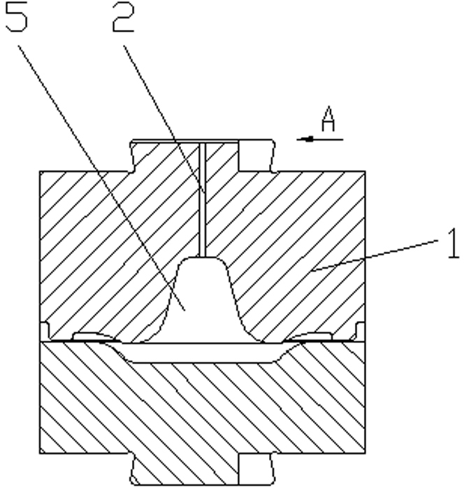
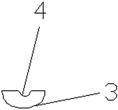
[0015] see Figure 2 to Figure 5 , a forging process for producing mushroom-shaped flanges on a die forging hammer. There is a valve at the center of the shaft of the mushroom-shaped flange corresponding to the pre-forging die chamber and the final forging die chamber to make the water vapor and air at the bottom of the die chamber timely The discharged vent hole 2, based on the function of the vent hole 2, is provided on the forging die corresponding to the center of the flange shaft. The diameter of the vent hole 2 directly affects the filling degree of the flange shaft end: if If the diameter of the vent hole 2 is large, the metal flow will be fast, and the filling degree of the shaft end will be better, but an obvious boss may be formed on the shaft end of the flange, which will affect the quality of the end face; if the diameter of the vent hole 2 ...


PUM

PropertyMeasurementUnit
diameteraaaaaaaaaa

Abstract

The invention relates to a forging process for producing a mushroom-shaped flange on a die forging hammer. In the process, exhaust holes through which water vapor and air at the bottom of a die cavity are exhausted in time are respectively arranged at the centers of a preforging die cavity and a finish forging die cavity, which correspond to shaft parts of a flange; and an exhaust groove is arranged on a dovetail plane of the forging die and vertical to and communicated with the exhaust holes. By respectively arranging the exhaust holes at the centers of the preforging die cavity and the finish forging die cavity, which correspond to shaft parts of the flange, the water vapor and the air at the bottom of the die cavity can be exhausted in time, the flowing resistance of metal can be greatly reduced when blanks are fully filled towards the shaft part of the flange, the flowing speed of the metal can be improved and the fully filling of the shaft part of the flange can be favored, therefore, the fullness of the shaft part of the flange can be ensured.

Description

technical field [0001] The invention belongs to the technical field of forging die design, and relates to a forging process for producing mushroom-shaped flanges on a die forging hammer and how to control metal flow in the forging forming process. Background technique [0002] Such as figure 1 Shown is a mushroom-shaped flange forging. The flange is shaped like a mushroom, so it is commonly called a mushroom-shaped flange. According to the shape and size requirements of the flange, combined with the previous forging process, it is necessary to It is difficult to ensure that the shaft portion of the flange is filled. [0003] For mushroom-shaped flanges, due to the large difference between the diameter of the shaft end (Ф84) (average diameter of the shaft Ф110) and the diameter of the flange (Ф550), it is difficult to meet the material distribution principle of the blank in the process, and it is impossible to ensure that the shaft is completely After calculation and analys...

Claims


Application Information

Patent Timeline
Patent Type & Authority Applications(China)
IPC IPC(8): B21J5/02
Inventor 张成婷尹云峰胡瑞强
Owner 广东省韶铸集团有限公司
Why Eureka
Eureka Blog
Learn More