
Lead pan for quenching steel wire

A lead pan and steel wire technology, applied in quenching devices, heat treatment equipment, furnaces, etc., can solve the problems of sharp cold cutting, aggravated pollution, easy brittle fracture, etc., and achieve the effects of reducing oxidation and volatilization, preventing contact and uniform performance.

Inactive Publication Date: 2011-04-13
苏闽(张家港)新型金属材料科技有限公司
View PDF4 Cites 3 Cited by
  • Summary
  • Abstract
  • Description
  • Claims
  • Application Information

AI Technical Summary

Problems solved by technology

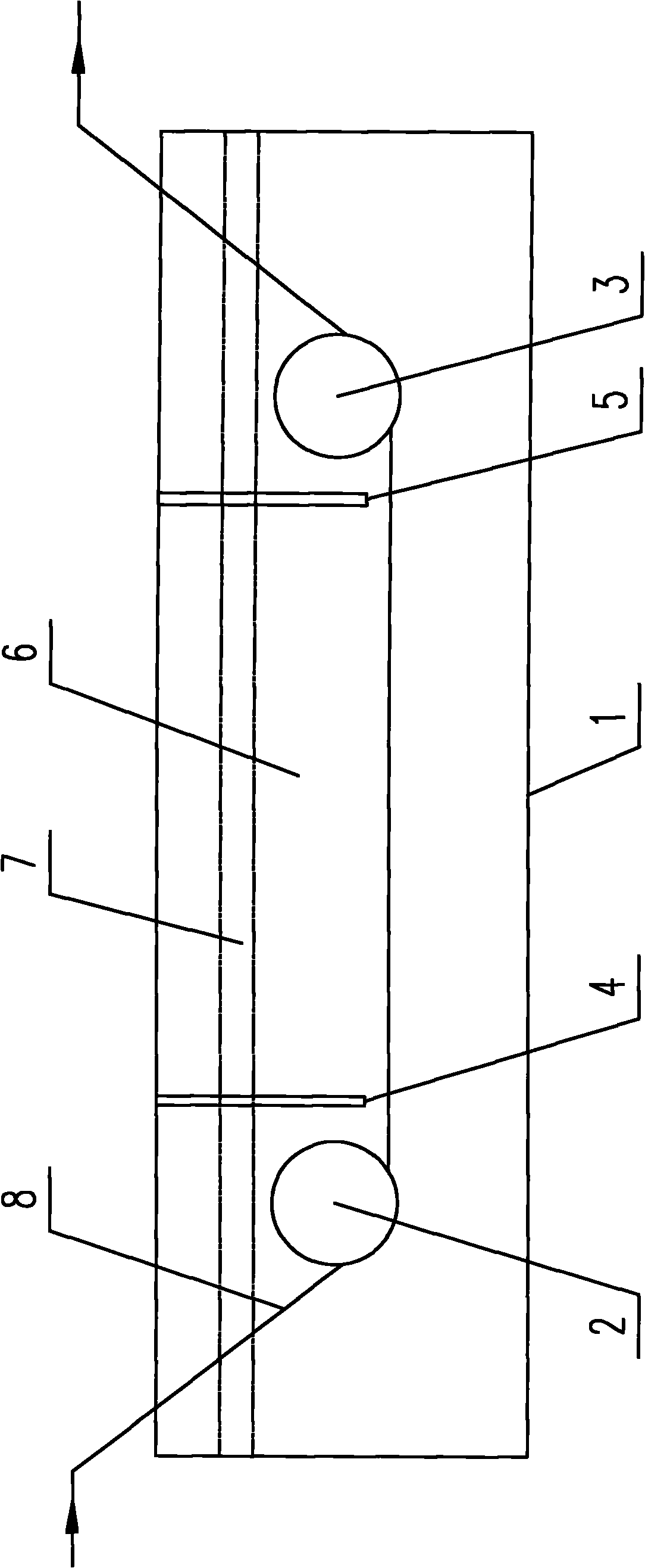
[0003] In the production operation, various operations are often required for the "transition zone" where the steel wire 6 enters the lead pot from the austenitic furnace and the "tail" where the steel wire 6 exits the lead pot: turning over the covering agent, replacing the covering agent, and repairing the lead pot. Pot accessories and normal wire threading operations, etc., so that the "transition zone" and "tail" of the lead pot will not form a lead oxide layer in a short time, but the "middle" section of the lead pot has a relatively large area and It takes a long time to clean up once. It is said that a lead oxide layer will be formed in the "middle" section of the lead pot, but during the operation of the "transition zone" and "tail" of the lead pot, the "middle" section of the lead pot The lead oxide layer will flow to the "transition section" and "tail" along with the flow of the lead liquid 4. When these lead oxide layers touch the running steel wire 6, they will dissolve immediately and absorb a large amount of heat at the same time, thereby causing the steel wire 6 The sharp cold cut of the steel wire 6 forms martensite, which makes the steel wire 6 easily brittle in the subsequent processing.
This drift of the "middle" lead oxide layer also causes the "middle" lead liquid to continuously oxidize, resulting in waste and aggravating pollution

Method used


Image

  • Lead pan for quenching steel wire
  • Lead pan for quenching steel wire
  • Lead pan for quenching steel wire

Examples


Embodiment Construction

[0014] The lead pot used for steel wire quenching of the present invention will be further described in detail below through specific examples.

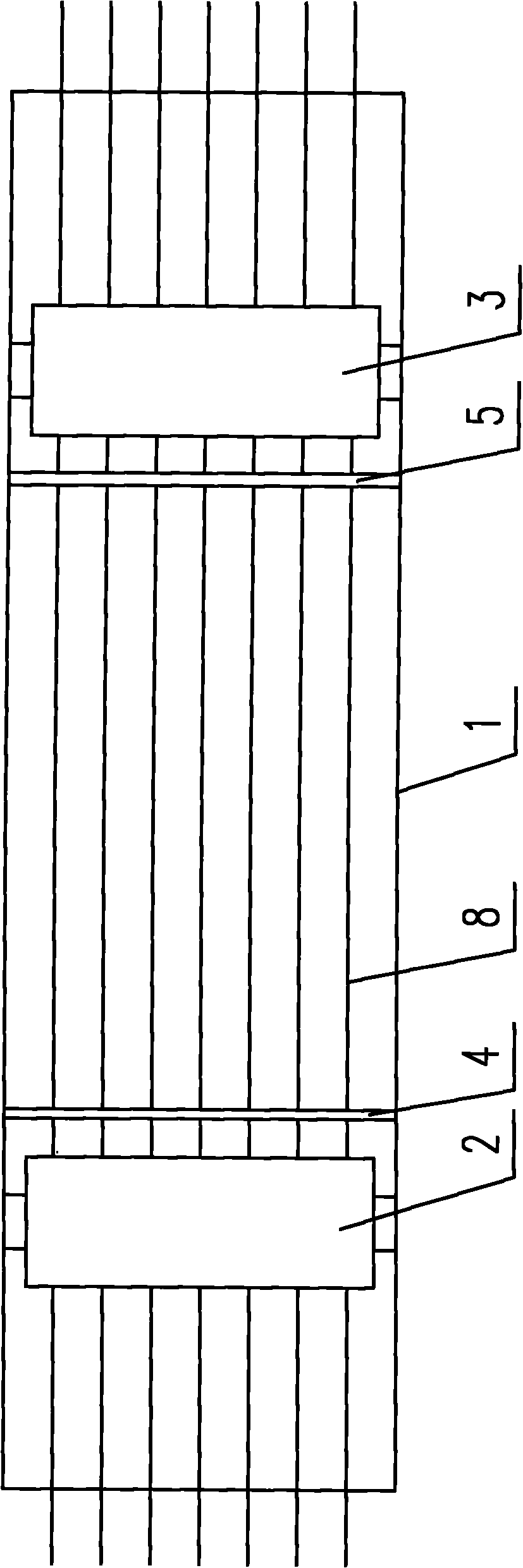
[0015] Such as figure 1 , figure 2 As shown, the lead pot used for steel wire quenching includes a pot body 1, the two ends of the pot body 1 are respectively provided with a left pressure roller 2 and a right pressure roller 3, and the two ends of the left pressure roller 2 and the right pressure roller 3 are respectively arranged On the side wall of the pot body 1, two baffle plates, a left baffle plate 4 and a right baffle plate 5, are arranged in the pot body 1, and the left baffle plate 4 is located on the right side of the left pressure roller 2, so The said right baffle 5 is located on the left side of the right pressure roller 3, and the two ends of the left baffle 4 and the right baffle 5 are respectively connected with the side wall of the pot body 1, that is, the said left baffle 4 and the right baffle 5 are respective...


PUM


Abstract

The invention relates to a lead pan for quenching a steel wire. The lead pan comprises a pot body, wherein a left pressing roll and a right pressing roll are arranged at both ends of the pot body respectively; both ends of the left pressing roll and the right pressing roll are arranged on the side wall of the pot body respectively; at least two baffle plates are arranged in the lead pot; both ends of each baffle plate are connected with the side wall of the pot body respectively; the baffle plates are positioned on the right side of the left pressing roll and the left side of the right pressing roll; and the lower parts of the baffle plates are positioned in lead liquid in the pot body. The lead pan is suitable for performing lead quenching on the steel wire by heat treatment in the production process of steel cords, rubber tube steel wires, steel strands and the like.

Description

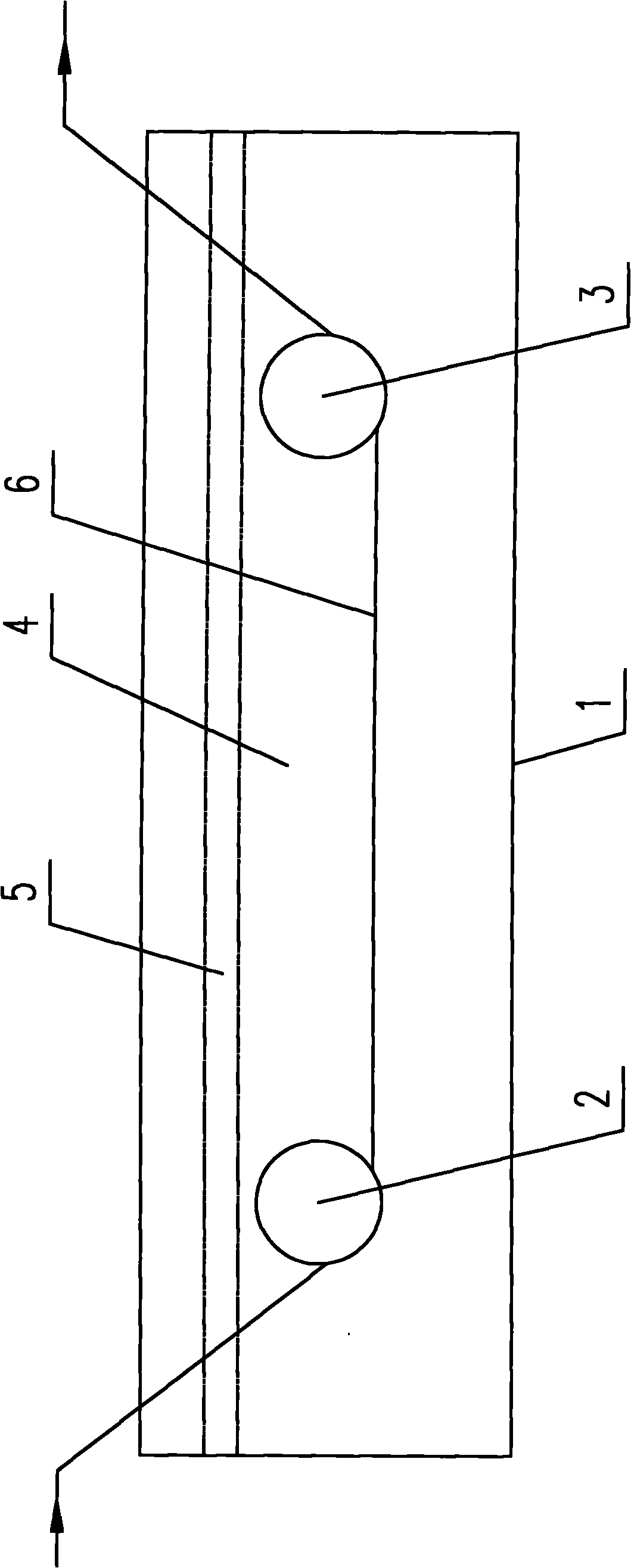
technical field [0001] The invention relates to a lead pot suitable for the steel wire heat treatment lead quenching process in the production process of steel cords, hose steel wires, steel strands and the like. Background technique [0002] In the production process of steel cord, hose steel wire, steel strand, etc., the steel wire must be lead-quenched. The structure of the currently used lead pot is as follows: image 3 , Figure 4 As shown, a pot body is included, and the two ends of the pot body 1 are respectively provided with a left pressure roller 2 and a right pressure roller 3, and the two ends of the left pressure roller 2 and the right pressure roller 3 are respectively installed on the side wall of the pot body 1, Lead liquid 4 is contained in the pot body 1, and a layer of covering agent 5 is arranged above the lead liquid 4 to prevent the oxidation and volatilization of the lead liquid 4, thereby achieving the purpose of saving costs, reducing environmental ...

Claims


Application Information

Patent Timeline
Patent Type & Authority Applications(China)
IPC IPC(8): C21D1/63C21D9/52
Inventor 吴晓玲
Owner 苏闽(张家港)新型金属材料科技有限公司
Learn More