Spherical elastic bearing and injecting method in forming process of spherical elastic bearing

An elastic bearing and glue injection technology, applied in the direction of flexible bearings, rigid supports of bearing components, bearings, etc., can solve problems such as deformation or lamination, insufficient rubber density, rubber and metal spacers, etc., to avoid deformation or lamination , Improve the fluidity of the glue and prevent the rubber from scorching

Active Publication Date: 2012-07-18
BAIMTEC MATERIAL CO LTD
View PDF0 Cites 0 Cited by
  • Summary
  • Abstract
  • Description
  • Claims
  • Application Information

AI Technical Summary

Problems solved by technology

[0003] The object of the present invention is: to propose a spherical elastic bearing and a glue injection method in the molding process of the spherical elastic bearing, to reduce the glue injection resistance and improve the fluidity of the glue; to avoid deformation or lamination of the spherical spacer; to prevent the rubber Solve problems such as scorch, uneven rubber vulcanization, insufficient rubber density, and failure of bonding between rubber and metal spacers, so as to improve the performance and fatigue life of elastic bearings

Method used


Image

  • Spherical elastic bearing and injecting method in forming process of spherical elastic bearing
  • Spherical elastic bearing and injecting method in forming process of spherical elastic bearing
  • Spherical elastic bearing and injecting method in forming process of spherical elastic bearing

Examples


Embodiment Construction

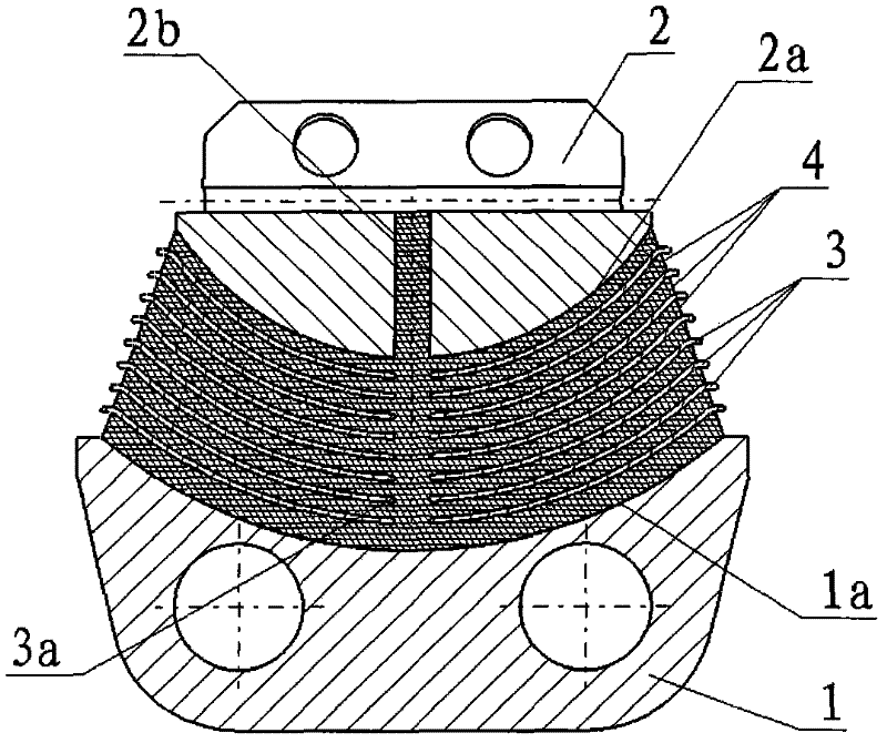
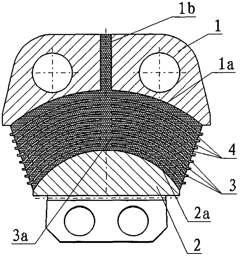
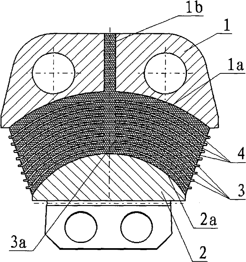
[0009] The present invention will be described in further detail below. see figure 2 , a spherical elastic bearing composed of a large joint 1, a small joint 2, 5 to 30 spherical spacers 3 and a rubber layer 4, the surface of the large joint 1 adjacent to the spherical spacer 3 is a concave concave spherical surface 1a, the small The surface of the joint 2 adjacent to the spherical spacer 3 is an upward convex convex spherical surface 2a. The spherical spacer 3 is a spherical metal sheet. All the spherical spacers 3 are stacked between the large joint 1 and the small joint 2 in sequence. The large joint 1 The concave spherical surface 1a of the spherical spacer 3 and the concave spherical surface 1a of the small joint 2 are all concentric, and there is a glue injection hole 3a in the center of the spherical spacer 3. Between the large joint 1 and the spherical spacer 3, adjacent There is a rubber layer 4 between the spherical spacer 3 and between the spherical spacer 3 and t...


PUM

PropertyMeasurementUnit
thicknessaaaaaaaaaa

Abstract

The invention belongs to a helicopter rotor spherical elastic bearing technique and relates to the improvement on a helicopter rotor spherical elastic bearing and an injecting method in the forming process of the spherical elastic bearing. In the spherical elastic bearing, a big joint injecting hole [1b] which runs through a big joint [1] along a center line of a concave spherical surface [1a] isformed in the center of the big joint [1]; the diameter of the big joint injecting hole [1b] is not less than that of an injecting hole [3a] of a spherical spacer [3]; and the big joint injecting hole [1b] is coaxially communicated with the injecting hole [3a] of the spherical spacer [3]. In the injecting method, the big joint [1] is arranged above; the outer end opening of the big joint injecting hole [1b] faces upwards; a small joint [2] is arranged below; and rubber is injected from the outer end opening of the big joint injecting hole [1b] by an injecting machine. By the spherical elasticbearing and the injecting method in the forming process of the spherical elastic bearing, the injecting resistance is reduced; the flowability of rubber liquid is improved; deformation or lamination of the spherical spacer is avoided; and the problems of scorch, non-uniform vulcanization and insufficient density of the rubber, bonding failure between the rubber and the metal spacer and the like are solved, so that the performance of the elastic bearing is improved and the fatigue life of the elastic bearing is prolonged.

Description

technical field [0001] The invention belongs to the helicopter rotor spherical elastic bearing technology, and relates to the improvement of the helicopter rotor spherical elastic bearing and the glue injection method in the process of forming the spherical elastic bearing. Background technique [0002] For the structure of the helicopter rotor spherical elastic bearing, see figure 1 , it consists of a large joint 1, a small joint 2, 5 to 30 spherical spacers 3 and a rubber layer 4, the surface of the large joint 1 adjacent to the spherical spacer 3 is a concave concave spherical surface 1a, and the small joint 2 is adjacent to the spherical spacer The surface of sheet 3 is an upward convex convex spherical surface 2a, spherical spacer 3 is a spherical metal sheet, all spherical spacers 3 are stacked between the large joint 1 and the small joint 2 in turn, the concave spherical surface 1a of the large joint 1, The spherical surface of the spherical spacer 3 and the concave ...

Claims


Application Information

Patent Timeline
Patent Type & Authority Patents(China)
IPC IPC(8): F16C27/00F16C27/06B64C27/35B29C39/02
Inventor 米志安蒋洪罡涂春潮赖亮庆王景鹤苏正涛
Owner BAIMTEC MATERIAL CO LTD
Why Eureka
Try Eureka